Grass Valley 2040RDA-16FR User Manual
Page 29
2040RDA-FR/16FR — Instruction Manual
29
Configuration and Adjustments
Status Web Page
Use
this
link
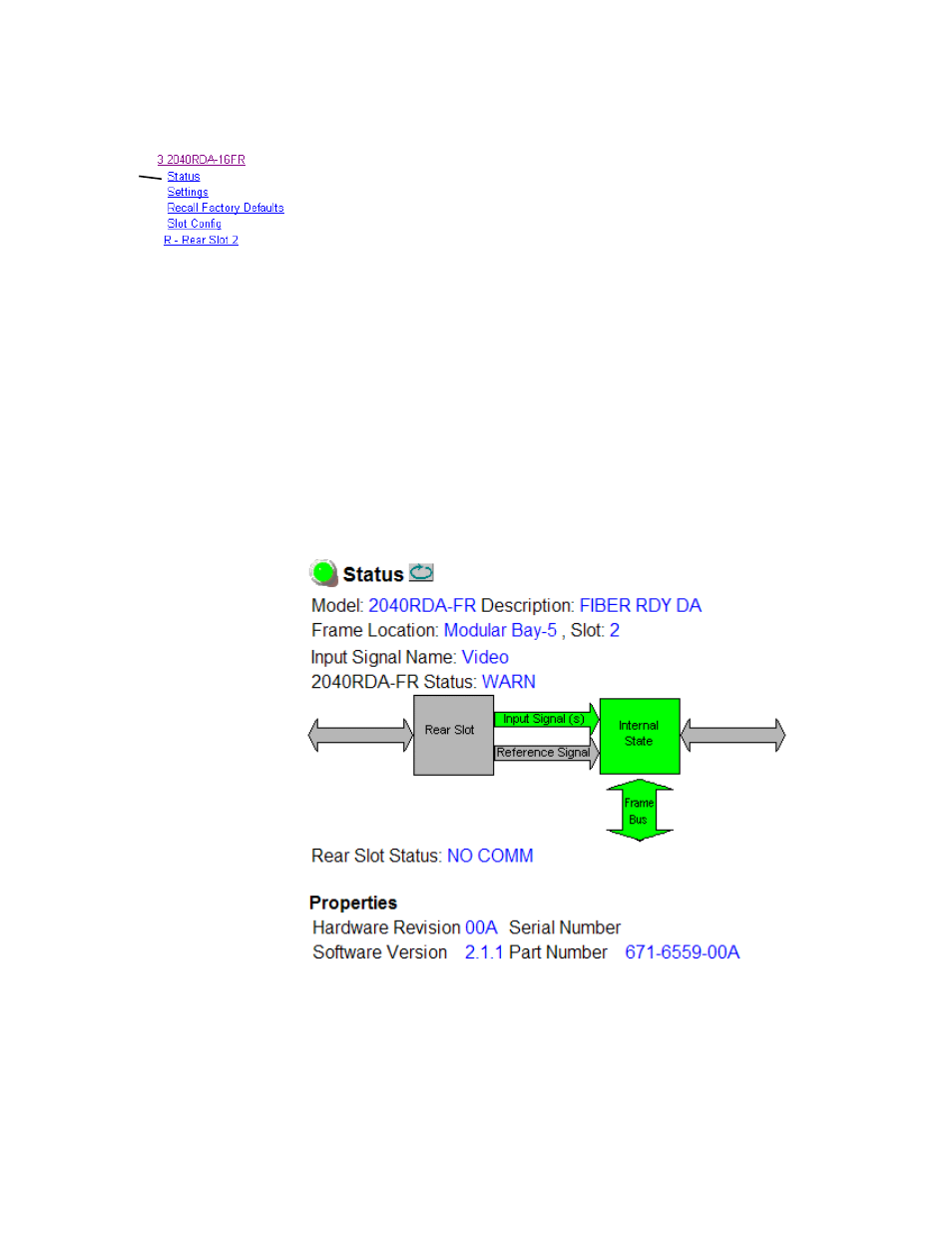
The Status web page (
for the 2040RDA-FR and
) shows the status of the input signal(s) and the frame bus commu-
nication. Color coding of the display indicates the signal status. In general,
colors used on the frame and modules indicate:
•
Green – normal operation, (Pass) or signal present, module locked.
•
Red – On continuously = fault condition, flashing = internal error.
•
Yellow – On continuously = active condition (configuration mode or
communication), flashing in sequence = module locator function.
Rear slot status is not reported from the passive rear module. If a wrong or
missing rear module is detected, the front edge FAULT LED will flash as
described in
and the Internal State block will be yellow
to report a Front/Rear module mismatch.
Information about the module, such as part number, serial number, hard-
ware revision and software and firmware versions are given in a read-only
Properties
section at the bottom of the display.
Figure 20. 2040RDA-FR Status Web Page