Mld snooping configuration examples, Network requirements, Configuration procedure – H3C Technologies H3C S3100V2 Series Switches User Manual
Page 87
79
NOTE:
•
The reset mld-snooping group command works on only an MLD snooping–enabled VLAN, but cannot
work on a VLAN with MLD enabled on its VLAN interface.
•
The reset mld-snooping group command cannot remove the static group entries of MLD snooping
groups.
•
For more information about the display mac-address multicast command, see the
IP Multicast
Command Reference.
MLD snooping configuration examples
IPv6 group policy and simulated joining configuration example
Network requirements
•
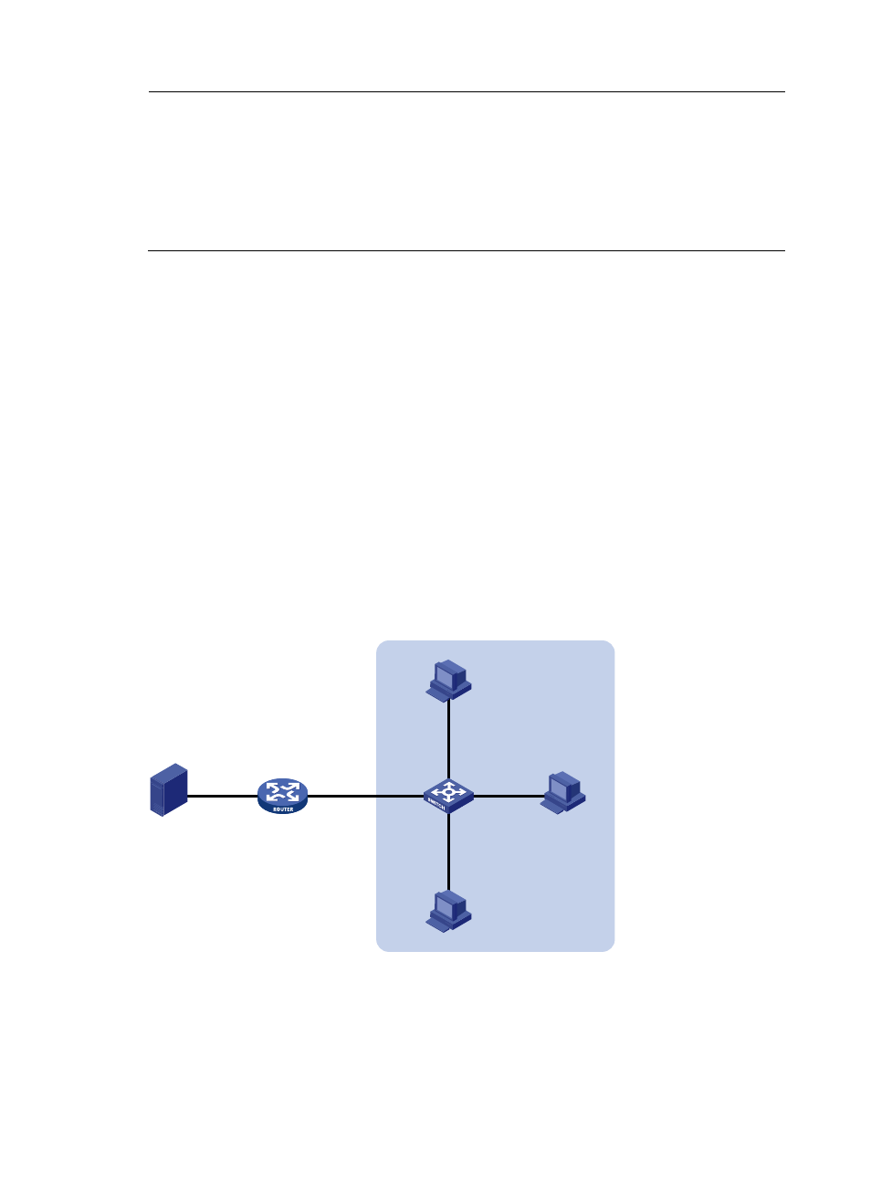
As shown in
, Router A connects to the IPv6 multicast source through Ethernet 1/0/2 and
to Switch A through Ethernet 1/0/1. Router A is the MLD querier on the subnet.
•
MLDv1 runs on Router A, MLDv1 snooping runs on Switch A, and Router A acts as the MLD querier
on the subnet.
•
The receivers, Host A and Host B, attached to Switch A can receive IPv6 multicast traffic addressed
to IPv6 multicast group FF1E::101 only.
•
IPv6 multicast data for group FF1E::101 can be forwarded through Ethernet 1/0/3 and Ethernet
1/0/4 of Switch A even if Host A and Host B accidentally, temporarily stop receiving IPv6 multicast
data.
Figure 24 Network diagram for IPv6 group policy simulated joining configuration
Source
Router A
MLD querier
Switch A
Receiver
Receiver
Host A
Host B
Host C
1::1/64
Eth1/0/4
Eth1/0/2
Eth1/0/3
Eth1/0/1
Eth1/0/1
2001::1/64
Eth1/0/2
1::2/64
VLAN 100
Configuration procedure
1.
Enable IPv6 forwarding and configure IPv6 addresses
Enable IPv6 forwarding and configure an IPv6 address and prefix length for each interface according to
. The detailed configuration steps are omitted.