Multicast vlan configuration examples, Port-based multicast vlan configuration, Network requirements – H3C Technologies H3C S3100V2 Series Switches User Manual
Page 63: Network diagram, Configuration procedure
55
Multicast VLAN configuration examples
Port-based multicast VLAN configuration
Network requirements
•
As shown in
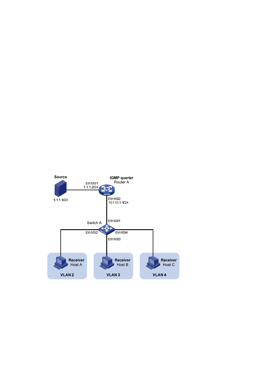
, Router A connects to a multicast source—Source—through Ethernet1/0/1,
and to Switch A through Ethernet1/0/2.
•
IGMPv2 is required on Router A. IGMPv2 snooping is required on Switch A. Router A acts as the
IGMP querier.
•
Switch A’s Ethernet1/0/1 belongs to VLAN 10, Ethernet1/0/2 through Ethernet1/0/4 belong to
VLAN 2 through VLAN 4 respectively, and Host A through Host C are attached to Ethernet1/0/2
through Ethernet1/0/4 of Switch A respectively.
•
The multicast source sends multicast data to multicast group 224.1.1.1. Host A, Host B, and Host C
are receivers of the multicast group.
•
Configure the port-based multicast VLAN feature so that Router A just sends multicast data to Switch
A through the multicast VLAN and Switch A forwards the multicast data to the receivers that belong
to different user VLANs.
Network diagram
Figure 20 Network diagram for port-based multicast VLAN configuration
Configuration procedure
1.
Configure IP addresses
Configure the IP address and subnet mask for each interface according to
. The detailed
configuration steps are omitted here.
2.
Configure Router A
# Enable IP multicast routing, enable PIM-DM on each interface, and enable IGMP on the host-side
interface Ethernet1/0/2.