Igmp snooping configuration examples, Network requirements, Configuration procedure – H3C Technologies H3C S3100V2 Series Switches User Manual
Page 42
34
IGMP snooping configuration examples
Group policy and simulated joining configuration example
Network requirements
•
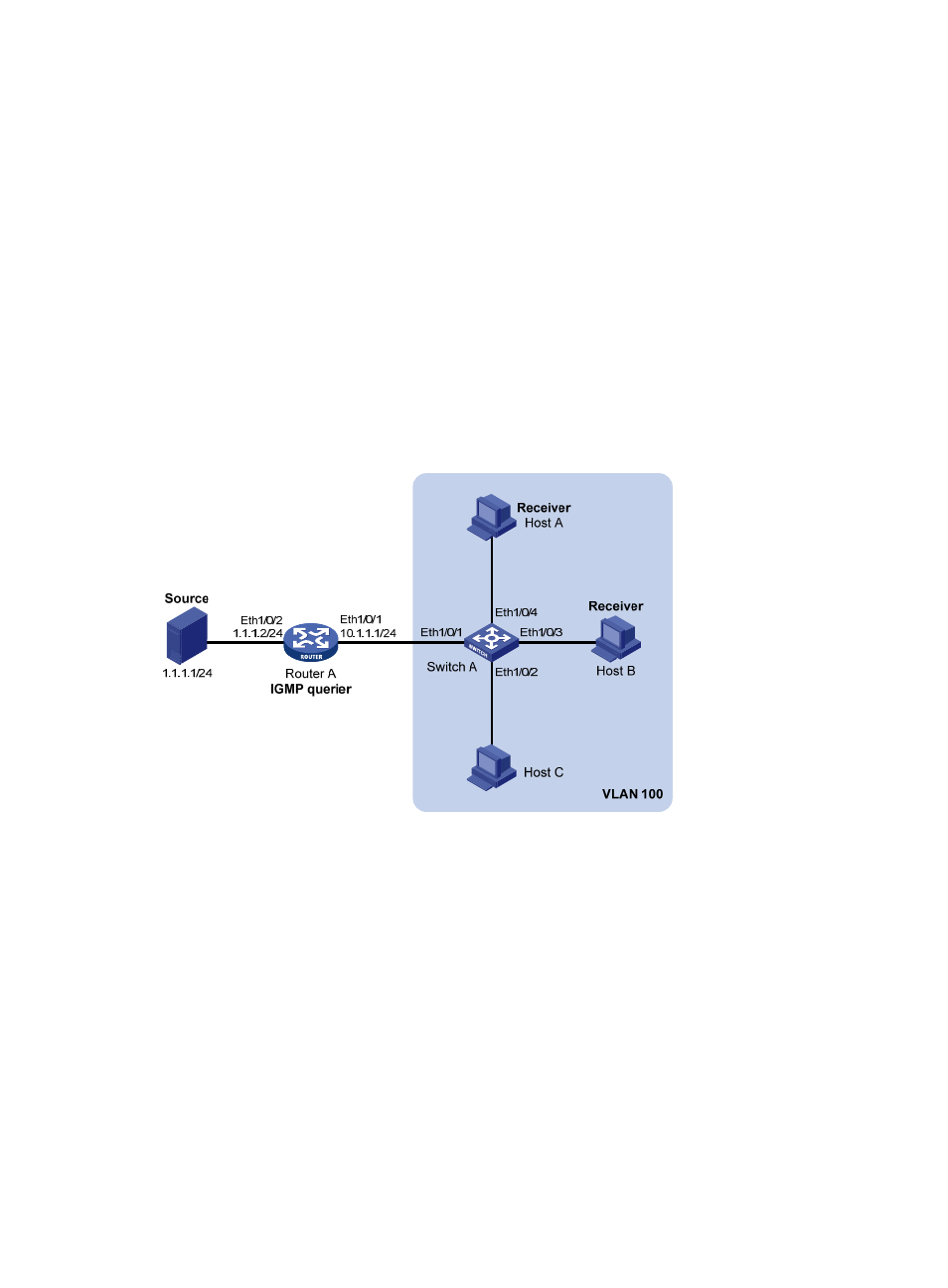
As shown in
, Router A connects to the multicast source through Ethernet 1/0/2 and to
Switch A through Ethernet 1/0/1.
•
IGMPv2 is required on Router A, IGMPv2 snooping is required on Switch A, and Router A will act
as the IGMP querier on the subnet.
•
The receivers, Host A and Host B, attached to Switch A can receive multicast traffic addressed to
multicast group 224.1.1.1 only.
•
Multicast data for group 224.1.1.1 can be forwarded through Ethernet 1/0/3 and Ethernet 1/0/4
of Switch A even if Host A and Host B accidentally, temporarily stop receiving multicast data.
Figure 13 Network diagram for group policy simulated joining configuration
Configuration procedure
1.
Configure IP addresses
Configure an IP address and subnet mask for each interface according to
. The detailed
configuration steps are omitted.
2.
Configure Router A
# Enable IP multicast routing, enable PIM-DM on each interface, and enable IGMP on Ethernet 1/0/1.
[RouterA] multicast routing-enable
[RouterA] interface ethernet 1/0/0/1
[RouterA-Ethernet1/0/1] igmp enable
[RouterA-Ethernet1/0/1] pim dm
[RouterA-Ethernet1/0/1] quit
[RouterA] interface ethernet 1/0/0/2
[RouterA-Ethernet1/0/2] pim dm