Pin assignments, Figure 61 – H3C Technologies H3C S3100V2 Series Switches User Manual
Page 67
61
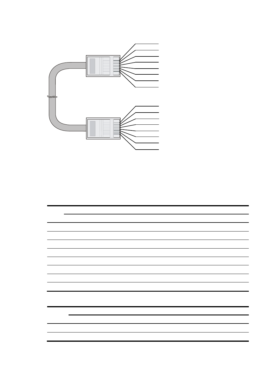
Figure 61 Crossover cable
Crossover cable
white/orange
orange
white/green
green
white/orange
orange
white/green
blue
white/blue
green
white/brown
brown
1
2
3
4
5
6
7
8
blue
white/blue
white/brown
brown
1
2
3
4
5
6
7
8
Pin assignments
Select an Ethernet twisted pair cable according to the RJ-45 Ethernet interface type on your device. An
RJ-45 Ethernet interface can be MDI (for routers and PCs) or MDIX (for switches). For the pinouts of RJ-45
Ethernet interfaces, see
Table 30 RJ-45 MDI interface pinouts
10Base-T/100Base-TX 1000Base-T
Pin
Signal Function
Signal
Function
1
Tx+
Send data
BIDA+
Bi-directional data cable A+
2
Tx-
Send data
BIDA-
Bi-directional data cable A+
3
Rx+
Receive data
BIDB+
Bi-directional data cable B+
4
Reserved
—
BIDC+
Bi-directional data cable C+
5
Reserved
—
BIDC-
Bi-directional data cable C
6
Rx-
Receive data
BIDB-
Bi-directional data cable B
7
Reserved
—
BIDD+
Bi-directional data cable D+
8
Reserved
—
BIDD-
Bi-directional data cable D-
Table 31 RJ-45 MDI-X interface pinouts
10Base-T/100Base-TX 1000Base-T
Pin
Signal Function Signal Function
1
Rx+
Receive data
BIDB+
Bi-directional data cable B+
2
Rx-
Receive data
BIDB-
Bi-directional data cable B-