Engineering labels for optical fibers – H3C Technologies H3C S7500E Series Switches User Manual
Page 152
142
Engineering labels for optical fibers
These labels are affixed to optical fibers that connect the fiber ports on the cards in a chassis, or connect
fiber ports on box-type devices. The following two types of labels are used for optical fibers:
•
Labels for a fiber that connects the fiber ports on two devices
Table 86 Information on labels affixed to the fiber between two devices
Content Meaning
Example
MN-B-C-D-R/T
MN—Rack number
•
M—Row number of the rack in the
equipment room, in the range of A to Z.
•
N—Column number of the rack in the
equipment room, in the range of 01 to 99.
For example, A01.
B—Chassis number
Numbered in top-down order with two digits,
for example, 01
C—Slot number
Numbered in top-down and left-right order
with two digits, for example, 01.
D—Fiber port number
Numbered in top-down and left-right order
with two digits, for example, 05.
R—Optical receiving interface
T—Optical transmitting interface
N/A
MN-B-C-D-R/T
MN—Rack number
The meanings are the same as above. If the
local device and the peer device are not in the
same equipment room, MN can be the name
of the equipment room.
B—Chassis number
C—Slot number
D—Fiber port number
R—Optical receiving interface
T—Optical transmitting interface
N/A
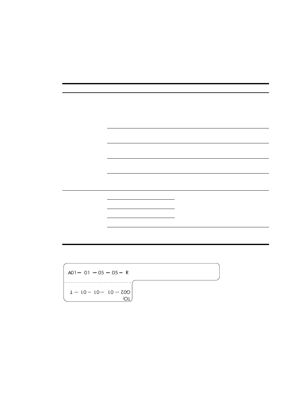
Figure 90 Example of a label on an optical fiber between two devices
{
A01-01-05-05-R—The local end of the optical fiber is connected to Optical Receiving Interface
05 on Slot 5, Chassis 01 in the rack on Row A, Column 01 in the equipment room.
{
G01-01-01-01-T—The peer end of the optical fiber is connected to Optical Transmitting Interface
01 on Slot 01, Chassis 01 in the rack on Row G, Column 01 in the equipment room
•
Labels for a fiber that connects the device and the optical distribution frame (ODF)