Module configuration and control, Front panel controls and indicators – Ensemble Designs 9400 3G Test Signal and Sync Pulse Generator User Manual
Page 25
www.ensembledesigns.com
Avenue 7400 and 9400 - Page 25
Model 7400 HD/SD and Model 9400 3G/HD/SD Sync Pulse Generator and Test Signal Generator
Module Configuration and Control
Avenue module parameters can be configured and controlled remotely from one or both of the
remote control options: the Avenue Touch Screen or the Avenue PC Application. Once the module
parameters have been set remotely, the information is stored on the module CPU. This allows
the module be moved to a different slot in the frame at your discretion without losing the stored
information.
Details for setting module parameters remotely using the Avenue PC option or the Avenue Touch
Screen option are described and illustrated in the “Avenue PC and Touch Screen Remote Configuration”
section of this manual.
7400
HD/SD
Dual
SPG/TSG
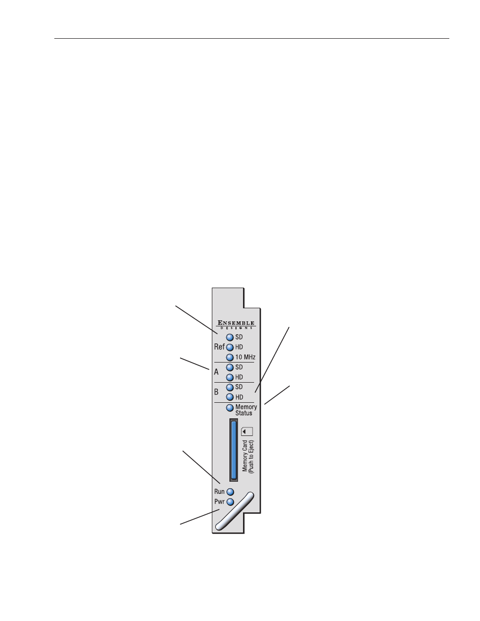
Ref SD, HD and 10 MHz
green LEDs:
One LED will light to indicate
which type of reference is
currently being detected.
If no LED is lit, no reference is
detected.
Generator A SD/HD
green LEDs:
One LED will light to indicate the
Primary output standard and that
it is locked to its timing source.
If no LED is lit, the Primary
generator is not locked to its
timing source.
Run green LED:
OFF: A power fault or halted CPU
ON: A halted CPU
FAST BLINK: CPU Run error
SLOW BLINK: System OK (If SPI
control is active from the main
frame System Control Module, all
module Run indicators will be
synchronized.)
Pwr green LED:
Indicates the presence (ON) or
absence (OFF) of power (+5V).
Generator B SD/HD
green LEDs:
One LED will light to indicate the
Primary output standard and that
it is locked to its timing source.
If no LED is lit, the Primary
generator is not locked to its
timing source.
Memory Status green LED:
LED flashes when memory is
being accessed. Illuminates green
when memory is available.
Front Panel Controls and Indicators
Each front edge indicator is shown in the diagram below: