5 rear panel – ARM Electronics RDVR16A User Manual
Page 10
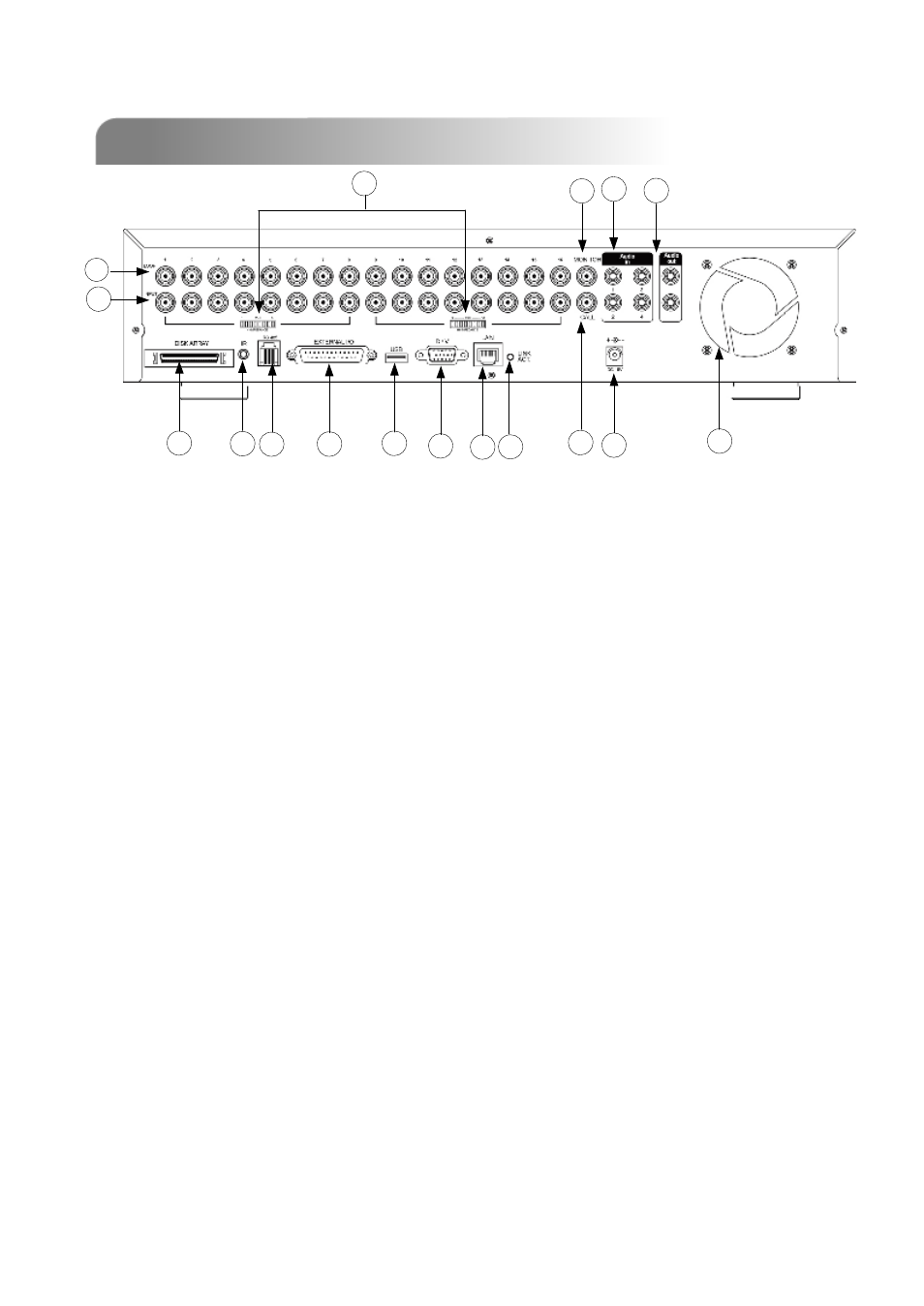
1)
DISK ARRAY PORT:
Connect to disk array for extend HDD capacity.
2)
IR:
Connect to IR receiver.
3)
RS485:
Connect to external device (such as PTZ camera) with RS485-A and RS485-B.
4)
EXTERNAL I/O PORT:
Connect to external device. Control external device or controlled remotely by
external device. Alarm input, external alarm.
5)
USB PORT:
Support firmware update and files backup.
6)
D/V PORT (Digital Video Port):
Connect to VGA connector card.
7)
LAN:
Connect to Internet by LAN cable.
8)
LINK / ACT LED light:
When the Internet is activated, the LED light will turn on.
9)
9)
CALL MONITOR:
CALL MONITOR:
Connect to CALL monitor. Show the Switch Display. When the alarm
Connect to CALL monitor. Show the Switch Display. When the alarm
is
is
triggered, the call monitor will show the triggered channel for
triggered, the call monitor will show the triggered channel for
a period of time.
a period of time.
1.5 REAR PANEL
1.5 REAR PANEL
15 16
17
13
12
1
2
3
4
5
6
7
8
10
9
11
14
6