Watson-Marlow Qdos30 Universal User Manual
Page 25
Watson-Marlow qdos30 Universal and Universal+ Pump User Manual
25
Configurable remote stop or contact input - J3
If Analog 4-20mA mode is selected then terminal J3
will be configured as a remote stop automatically.
If Contact mode is selected then the input J3 will
be configured as a contact input automatically.
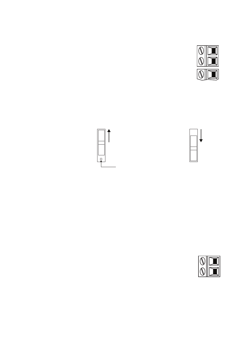
Rem Stop
+24V
Stop/contact
1
2
J3
GND
2
J2
Remote stop
Connect a remote switch between the Stop/Contact terminal and the +24V
terminal of the Run/Stop I/P connector (J3). Alternatively a 24V logic input may be
applied to the Stop/Contact terminal, ground to the GND terminal of the adjacent
4-20mA I/P connector (J2).
The sense of the remote stop input can be set using the dip switch (SW1).
N/C
N/O
SW1
Dimple
N/C
N/O
SW1
To set the logic sense as N/C the switch
should be set to the left (up as you look
at the switch). A dimple will be visible
(as shown) which confirms N/C.
To set the logic sense as N/O the switch
should be set to the right (down as you
look at the switch). No dimple will be
visible (as shown) which confirms N/O.
When the dip switch is set to N/O; high input stops the pump, low input runs the
pump. With no connection or with the switch open, the pump will default to running.
When the dip switch is set to N/C; low input stops the pump, high input runs the
pump. With no connection or with the switch open, the pump will default to stop.
Remote stop is operational in manual and analogue mode.
Contact
To operate the pump in contact mode the dip switch should always be set for N/O.
Speed: analogue input (J2)
The analogue process signal must be applied to the I/P
terminal of the Analogue connector (J2). Ground to the
GND connector of the same terminal. In Analogue mode
the pump set speed will be proportional or inversely
proportional to the analogue input. See also 15.5 Analog
4-20mA mode on page 37 and 15.6 Calibrate the pump
for 4-20mA control on page 41.
4-20mA circuit impedance: 250Ω.
Max current 40mA
Note: inverting the signal response is set up in software.
Do not invert the polarity of the terminals.
Analog
I/P
GND
1
2
J2