3 24 volt relay module pcb connectors, Alarm output (j5), Rly1 – Watson-Marlow Qdos30 Universal User Manual
Page 24: Cn/c 2 3 n/o 1 run status output (j4), Rly2 c n/c 2 3 n/o 1
Watson-Marlow qdos30 Universal and Universal+ Pump User Manual
24
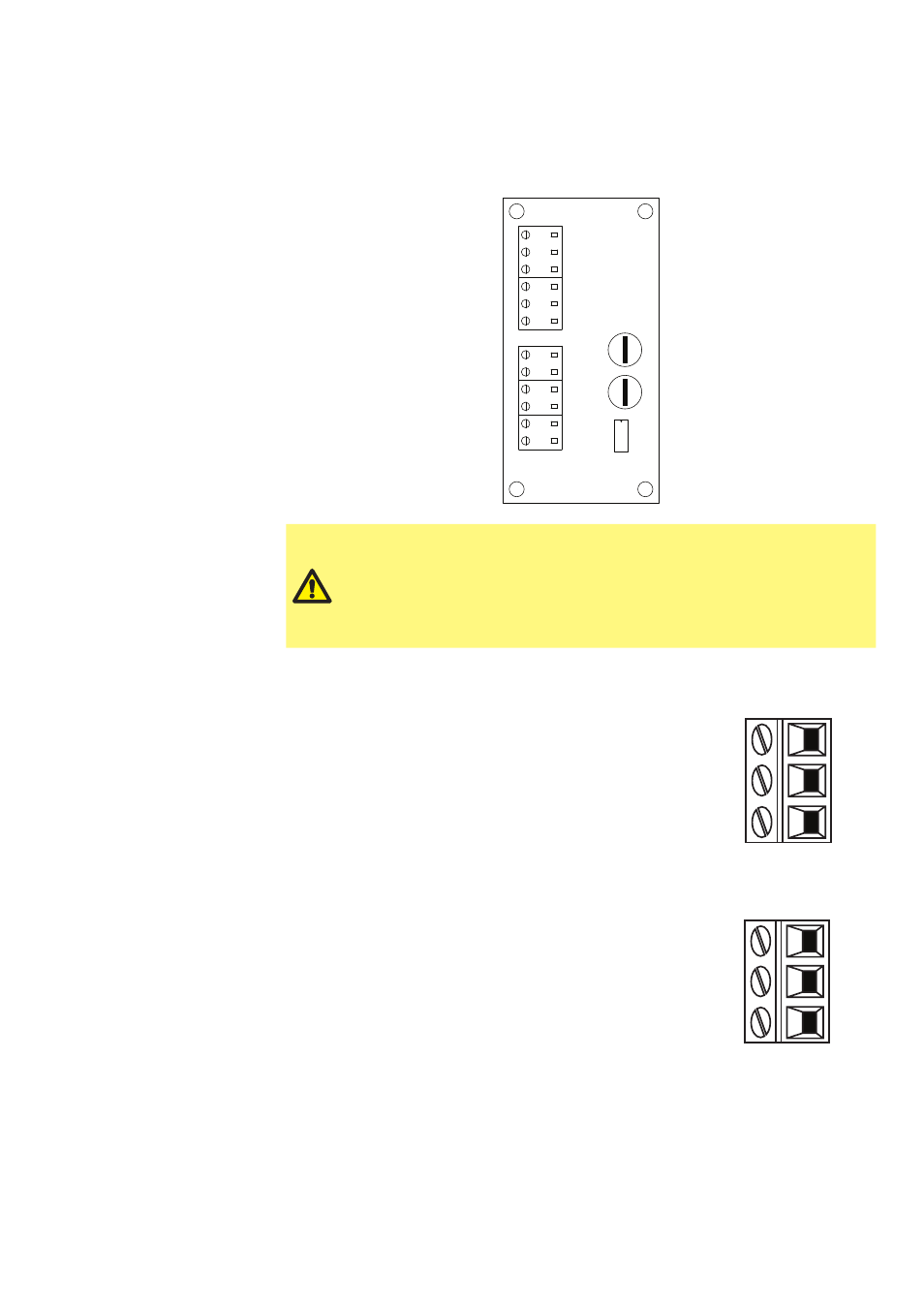
12.3 24 volt relay module pcb connectors
As you look at the module the pcb will appear in the same orientation as shown in
the diagram below.
RL
Y1
RL
Y2
4-20mA
J1
1
2
1
2
1
2
1
3
1
3
J2
J3
7J
6J
O/P
GND
I/P
GND
+24V
Contact
N/O
N/C
C
N/O
N/C
C
J4
J5
4-20mA
Stop/
N/C
N/O
Stop/Contact
SW1
Never apply mains power to the terminals within a qdos30 24V
relay module. Apply the correct signals to the terminals shown
below. Limit signals to the maximum values shown. Do not apply
voltage across other terminals. Permanent damage, not covered
by warranty, may result. The maximum load on the relay contacts
of this pump is 24VDC at 1.0A. Note that the maximum switching
capacity on DC is 30W.
Alarm output (J5)
Connect the output device to the C (common) terminal of
the relay connector and either the N/C (normally closed) or
N/O (normally open) terminal as required.
This relay coil is energised when the pump has an alarm
condition.
Note: Alarm conditions are generated by system errors.
This alarm will not be operated for analogue signal errors.
RLY1
J5
C
N/C
2
3
N/O
1
Run status output (J4)
Connect the output device to the C (common) terminal of
the relay connector and either the N/C (normally closed) or
N/O (normally open) terminal as required.
This relay coil is energised when the pump is running.
RLY2
C
N/C
2
3
N/O
1
J4