11 automatic control wiring - standard pump, 1 input pin assignments at the pump – Watson-Marlow Qdos30 Universal User Manual
Page 17
Watson-Marlow qdos30 Universal and Universal+ Pump User Manual
17
11 Automatic control wiring -
standard pump
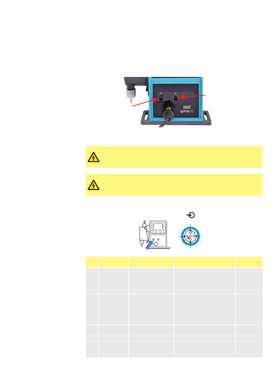
Interfacing the pump with other devices is by means of two IP66 rated five pole
M12 connectors mounted on the front of the pump. M12 connectors with flying lead
cables can be purchased as an accessory from Watson-Marlow. The function of each
of the leads is labelled.
Output
connection
Input
connection
It is the user’s responsibility to ensure the safe and reliable operation of the pump
under remote and automatic control.
Never apply mains power to the five pole M12 connectors. Apply
the correct signals to the pins, as shown below. Limit signals to
the maximum values shown. Do not apply voltage across other
terminals. Permanent damage may result.
All input and output terminals are separated from mains circuits
by reinforced insulation. These terminals must only be connected
to external circuits that are also separated from mains voltages by
reinforced insulation as a minimum requirement.
11.1 Input pin assignments at the pump
Pin 2
Pin 4
Pin 1
Pin 3
Pin 5
Pin
No.
Function
Specification
Referenced to
Input lead
colour
1
Run/stop
Min. 5V, max. 30V
Connect 5–24V DC supply to
stop (referenced to pin 4)
Alternatively connect pin 5 of
the output connector to this
pin via normally open switch
Brown
2
External
contact
Min. 5V, max. 30V
Pulse 5–24V
40ms minimum pulse length
(referenced to pin 4)
Alternatively connect pin 5 of
the output connector to this
pin via normally open switch
White
3
4-20mA
250
W input impedence
40mA max. current
Referenced to GND
Blue
4
GND
Ground (0V)
Black
5
Remote fluid
recovery
Min. 5V, max. 30V
Connect 5–24V DC supply
to reverse the pump in
analog mode
Grey