3 output pin assignments at the pump – Watson-Marlow Qdos30 Universal User Manual
Page 19
Watson-Marlow qdos30 Universal and Universal+ Pump User Manual
19
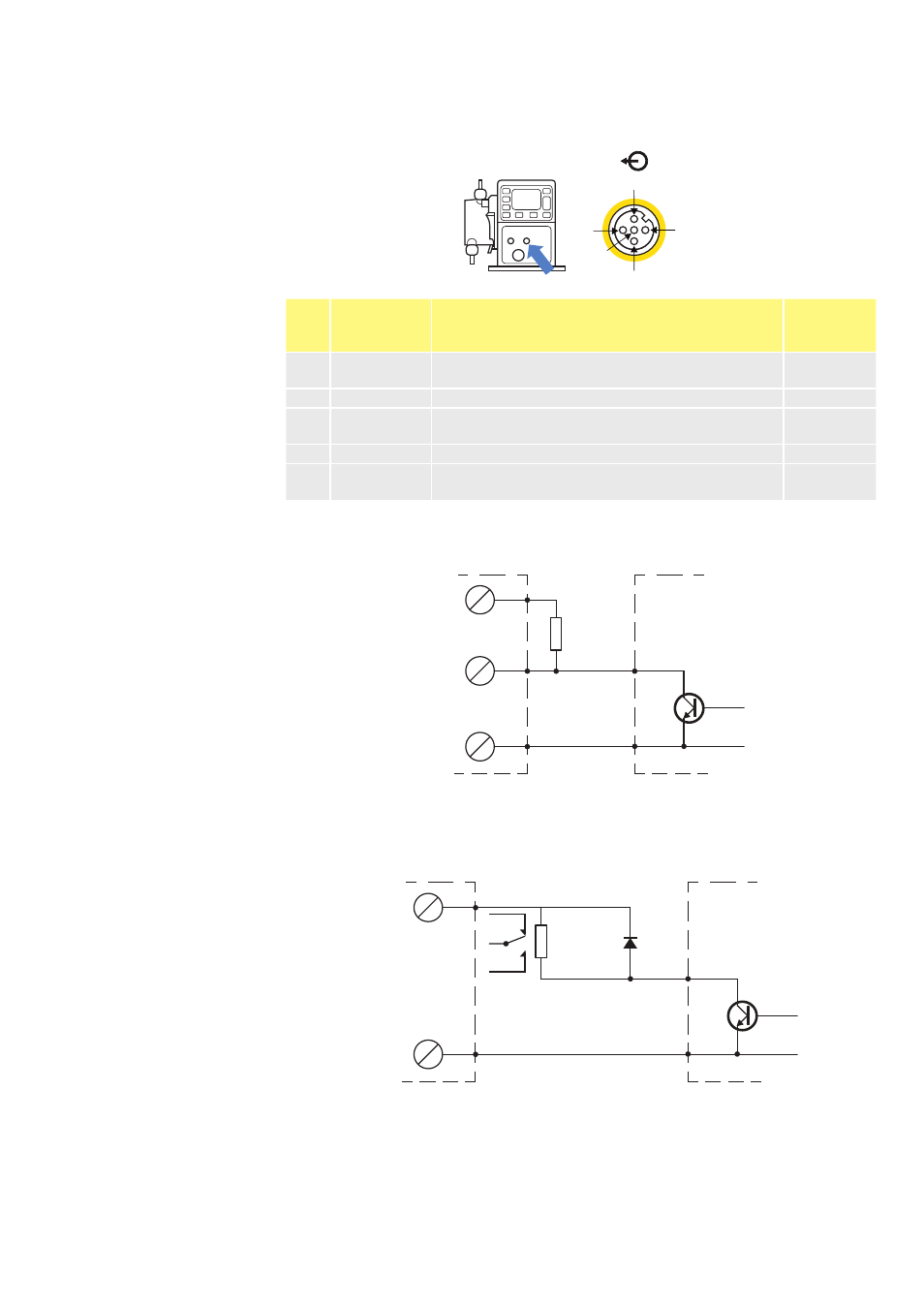
11.3 Output pin assignments at the pump
Pin 2
Pin 4
Pin 1
Pin 3
Pin 5
Pin
No.
Function
Specification
Output
lead
colour
1
Run/status
output
Open collector output uncommitted
Brown
2
Alarm output Open collector output uncommitted
White
3
Analog out
4-20mA into 250Ω (referenced to pin 4)
(Universal+ only)
Blue
4
GND
Black
5
Supply
5V 20mA, this can be connected via a NO
switch to input pin 1 or 2 to power the inputs.
Grey
Example wiring for a “pull up resistor”
Diagram depicts either Alarm or Run Stop output.
1K2 Minimum
2K2 Typical
+24V
Input
Common
qdos
PLC
Example wiring for an external relay, the NO or NC contacts could be
used to drive any device.
Diagram depicts either Alarm or Run Status output.
2K2 Typical
1K2 Minimum
1A 100V
+24V
Common
qdos
PLC
The resistor or relay needs to be sized correctly to ensure no damage to the pump
transistors. These solutions require external 24V power. If connecting to a PLC
24V is usually available.