12 automatic control wiring - module, 1 module: cover removal and refitting – Watson-Marlow Qdos30 Universal User Manual
Page 21
Watson-Marlow qdos30 Universal and Universal+ Pump User Manual
21
12 Automatic control wiring -
module
The pump can be connected with other devices by means of the screw-terminal
connectors within the 24 volt relay module situated on the side of the pump. The
relay module must be removed from the pump housing to allow suitable cables to be
connected to the terminal connectors via the watertight cable glands on the module.
12.1 Module: cover removal and refitting
Removing the 24 volt relay module cover
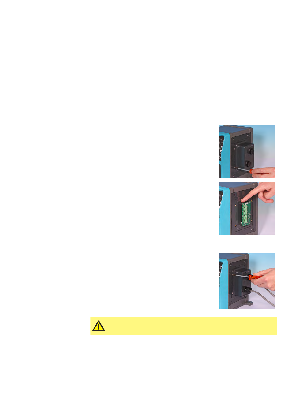
The module cover is secured to the side of the drive unit by four M3x10 Pozidriv pan
head stainless steel screws.
Remove the four screws from the module cover,
leaving the top left screw until last. It is possible that
the sealing strip may cause the module to adhere to
the drive housing. If so, a gentle tap will free it. Do
not use a tool to force it off.
The sealing strip should be retained within its channel
on the side panel of the drive housing. It ensures
ingress protection between the drive housing and the
module cover. Check the integrity of the sealing strip.
If it is damaged it must be replaced.
Refitting the 24 volt relay module cover
Ensure the sealing strip is undamaged and positioned
within its channel on the side of the drive housing.
Hold the module cover in place, taking care not to
disturb the sealing strip. Starting with the top left
screw, tighten the four retaining screws to 2.5Nm.
Ensure that the 24 volt logic module cover is correctly secured at
all times by all four screws. Failure to do so may compromise the
IP66 (NEMA 4X) protection.