Users manual, Mc100, 1 network node address switches s1/s2 – Watson-Marlow MC100 User Manual
Page 14: 2 p1/p2 led indicators
Users Manual
MC100
MC100 DeviceNet OM 1.15 EN
Version: 1.04
Page 14 of 43
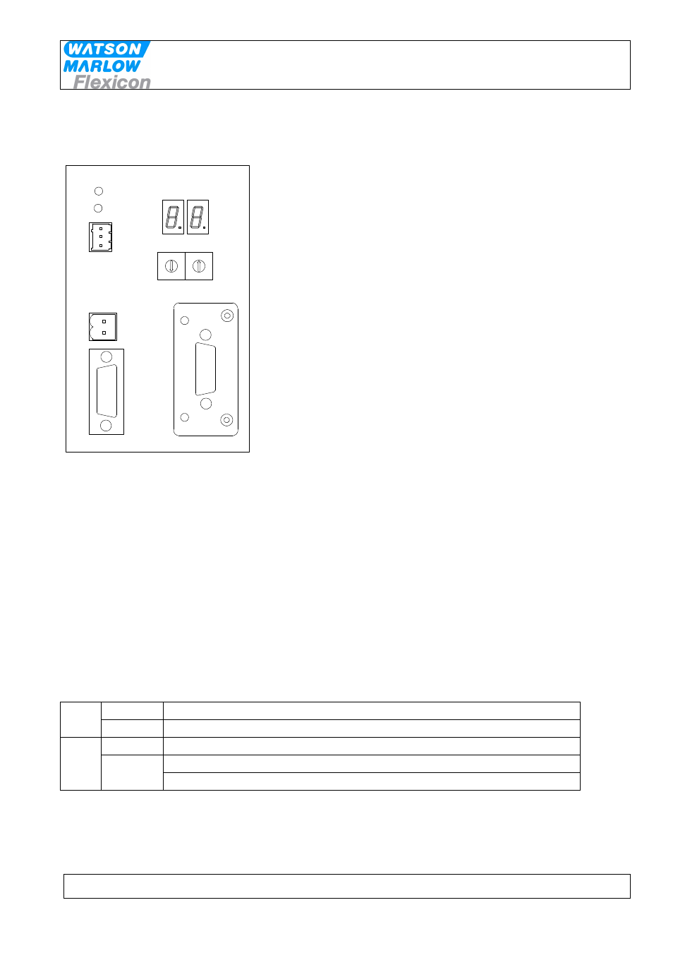
5 Fieldbus network node address and front plate indicators
MC100 Frontplate
1 0
3
4
9
6
8
5
7
2
1 0
3
4
9
6
8
5
7
2
Con 4
Connectors / Indicators / Switches
COMM
BUSY
Con 3
Con 2
Con 1
1
1
2
2
3
X10
X1
Address
5.1 Network node address switches S1/S2:
The node address is setup on the 2 rotary switches S1 and S2.
Address-range
1 to 99
The address is normally set before powering up and connecting to the network for the first time, but if
the address is change after power up, the new address will flash on P4/P5 display for 5 seconds,
where it is possible to change back to the old address.
After 5 seconds the MC100 will do a total factory reset and start up using the new address.
5.2 P1/P2 LED indicators:
P1
Green
Continuously ON or flashing indication communication with the pumps
Red
Flashing indicates Lost connection to at least 1 pump or internal error
P2
Green
Currently not used
Red
ON indicates at least 1 pump is active
Flashing together with P1 indicate fatal internal error in the module.