Secondary installation – Enviro Haven Direct Vent Fireplace User Manual
Page 30
Secondary Installation
QUALIFIED INSTALLERS ONLY
O
PTIONAL
F
AN
K
IT
I
NSTALLATION
:
If the Haven is installed the burner and valve assemblies must be removed. If the Haven is not installed
the fan can be installed through an access hole at the lower rear of the unit.
CAUTION: When servicing controls, label all wires prior to disconnection. Wiring errors can cause
improper and dangerous operation. Verify proper operation after servicing.
Kit Contents:
This kit includes a fan assembly, a wiring harness, a temperature sensor, fan control dial, two (2)
grommets, and two (2) 8-32 x 3⁄4” bolts.
Please ensure that your fan kit has not been damaged. If so, contact your dealer, distributor, or courier
company before starting this installation.
O
PTIONAL
F
AN
K
IT
I
NSTALLATION
T
HROUGH
B
ACK
OF
H
AVEN
:
1. Use a flat head screwdriver or a 1⁄4” socket to remove the six (6) screws holding the back cover on
(see Figure 44).
2. Remove the two (2) bottom screws holding the stand-off on (see Figure 45) and swing it out of the
way.
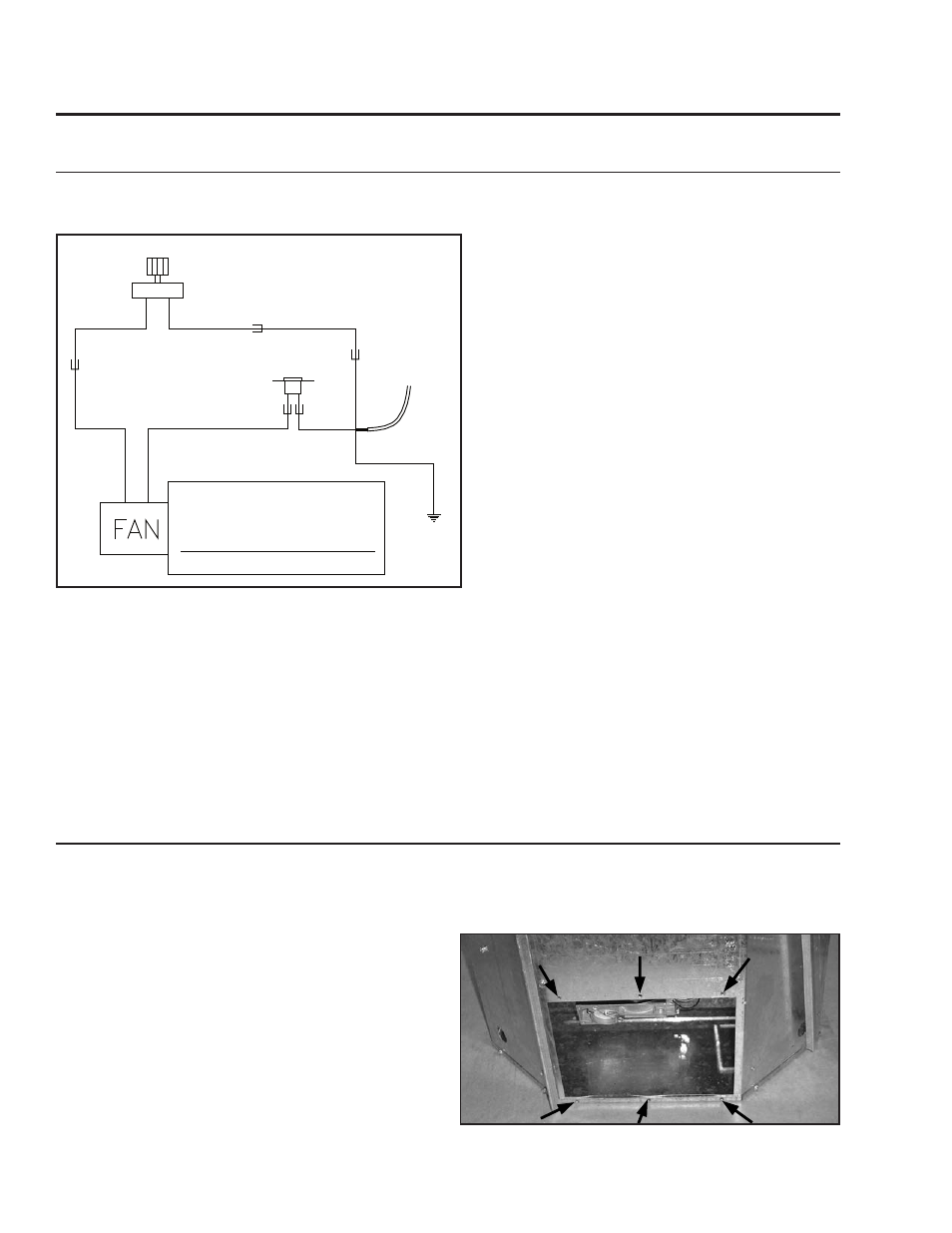
Figure 43. Wiring Diagram For Fan Control.
The optional fan is thermostatically controlled
and it will not operate if the appliance is cold.
A few minutes after the appliance is lit and the
variable speed control is set at a desired setting,
the fan will automatically turn on. The fan will
automatically turn off a few minutes after the
appliance is shut off.
The fireplace must be electrically connected and
grounded in accordance with local codes or, in
the absence of local codes, with the current CSA
C22.1 Canadian Electrical Code Part 1, Safety
Standards For Electrical Installations, or The
National Electrical Code ANSI / NFPA 70 in the
US.
WARNING: The electrical grounding instructions
must be followed. The fan should be properly
grounded.
Fan Control
Black
Black
Black
Long
Black
Short
Black
Electrical
Power Cord
White
White
Green
120
o
F (49
o
C)
Temperature
Sensor
Figure 44: Removing Back Plate From Haven.
3. Install the two (2) grommets; place a 8-32 x 3⁄4”
bolt through each grommet then attach the bolt
to the back cover using a 1⁄4” socket.
4. Ensure the wiring harness is attached to the fan
then hook the two (2) slots on the fan box over
the grommets installed in the last step.
5. Slide the fan with the wiring harness attached
into the hole in the back of the haven, motor side
first (see Figure 46).
30