Initial installation, Qualified installers only – Enviro Haven Direct Vent Fireplace User Manual
Page 28
I
NSTALLATION
O
F
E
LECTRICAL
W
IRING
F
OR
T
HE
O
PTIONAL
F
AN
K
IT
:
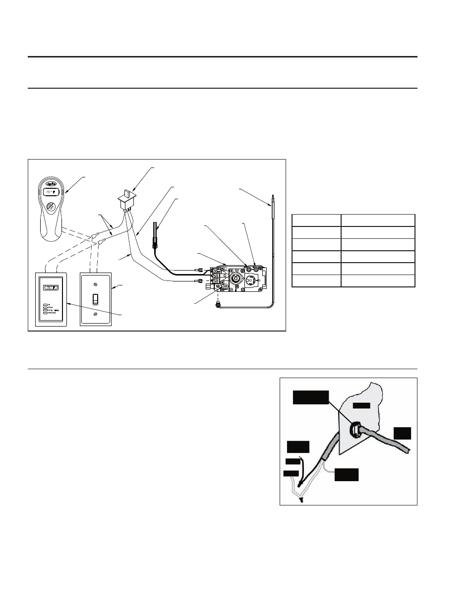
Figure 40. Wiring Diagram For Gas Valve.
COOL / HEAT
PROGRAM
DOWN
UP
70 ° F
70 ° F
ON
OF
F
Optional
Remote
Control
ON/OFF/Remote
Thermostat Switch
Purple
Thermocouple
Blue
Thermopile
Grey
Inlet
Pressure
Tap
Gas Control
Valve
Manifold
Pressure Tap
Pilot Adjustment
Screw
Optional
Wall Switch
Optional
Thermostat
Wire Size
Max. Length
14 gauge
100 ft (30.48 m)
16 gauge
60 ft (18.29 m)
18 gauge
40 ft (12.00 m)
20 gauge
25 ft (7.62 m)
22 gauge
18 ft (5.49 m)
Table 8. Recommended Thermostat
Wire Size.
Figure 41. Install Electrical 14/2 Wire
Power Cable Into Haven.
The electric 14/2 wire power cable must be hard wired to the
bottom left (or right or bottom if the gas line is to come in on the
left) of the unit if a fan is currently installed, or if you plan to install
the Optional Fan Kit (50-1211) in the future.
Refer to local electrical bylaw for proper installation. In the absence
of local codes, with the current CSA C22.1 Canadian Electrical
Code Part 1, Safety Standards For Electrical Installations, or The
Current National Electrical Code ANSI / NFPA 70 in the US.
Use a strain relief or cable clamp to attach the wiring to the unit.
WARNING: Ensure that the power is turned of to the lead from the
source BEFORE conducting any wiring.
E
LECTRICAL
S
YSTEM
F
OR
T
HERMOSTAT
:
CAUTION: Label all wires prior to disconnection when servicing controls. Wiring errors can cause
improper and dangerous operation. Verify proper operation after servicing.
20ft (6.1m) of bell wire is included with this unit. Determine the desired location of the thermostat or
wall switch (if used). Connect the bell wire to the valve as shown and run it to the desired location for
the thermostat or wall switch and make the connection.
Initial Installation
QUALIFIED INSTALLERS ONLY
28