Verilink QPRI 2921 (880-503143-001) Product Manual User Manual
Page 37
Configuring the QPRI 2921 Via the NCM 2000 Craft Interface
Verilink QPRI 2921
3-3
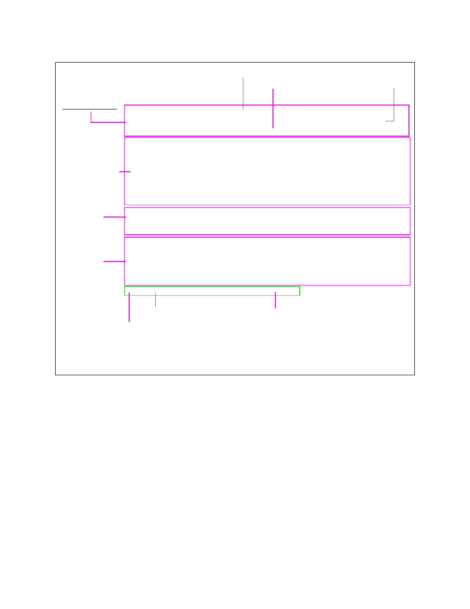
Figure 3-1 NCM Main Menu
The node master is the module responsible for:
•
Collecting alarm information for the node.
•
Controlling the relay responsible for reflecting the node’s
alarm status. (The relay is activated if any module is in major
or critical alarm status. See the NCM 2000 User Manual.)
•
Controlling circuit builder.
Menus and reports are available for the QPRI 2921 via the NCM
2000 by using the S (shelf/slot) option of the NCM Main Menu to
select a QPRI module.
-- VERILINK NCM CONTROLLER : FW Rev 4.15, Dec 13 1997 12:53:30 --
-- VERILINK NCM CONTROLLER : FW Rev 4.15, Dec 13 1997 12:53:30 --
-- VERILINK NCM CONTROLLER : FW Rev 4.15, Dec 13 1997 12:53:30 --
-- VERILINK NCM CONTROLLER : FW Rev 4.15, Dec 13 1997 12:53:30 --
Site Name: Verilink Test Access Level: 2
Site Name: Verilink Test Access Level: 2
Site Name: Verilink Test Access Level: 2
Site Name: Verilink Test Access Level: 2
Managing at NEAR end node [127.255.255.0] Node ID: 0
Managing at NEAR end node [127.255.255.0] Node ID: 0
Managing at NEAR end node [127.255.255.0] Node ID: 0
Managing at NEAR end node [127.255.255.0] Node ID: 0
<- SLOT ->
<- SLOT ->
<- SLOT ->
<- SLOT ->
SHELF 1 2 3 4 5 6 7 8 9 10 11 12 13
SHELF 1 2 3 4 5 6 7 8 9 10 11 12 13
SHELF 1 2 3 4 5 6 7 8 9 10 11 12 13
SHELF 1 2 3 4 5 6 7 8 9 10 11 12 13
0 - - - - - - - - - - - - -
0 - - - - - - - - - - - - -
0 - - - - - - - - - - - - -
0 - - - - - - - - - - - - -
1 D *N [X]
1 D *N [X]
1 D *N [X]
1 D *N [X]
2 - - - - - - - - - - - - -
2 - - - - - - - - - - - - -
2 - - - - - - - - - - - - -
2 - - - - - - - - - - - - -
3 - - - - - - - - - - - - -
3 - - - - - - - - - - - - -
3 - - - - - - - - - - - - -
3 - - - - - - - - - - - - -
4 - - - - - - - - - - - - -
4 - - - - - - - - - - - - -
4 - - - - - - - - - - - - -
4 - - - - - - - - - - - - -
KEY: A=DIDCSU, B=DIU/DBU, C=CSU, D=DIU, E=SDIU, F=DIU/DDS, G=DHDM,
KEY: A=DIDCSU, B=DIU/DBU, C=CSU, D=DIU, E=SDIU, F=DIU/DDS, G=DHDM,
KEY: A=DIDCSU, B=DIU/DBU, C=CSU, D=DIU, E=SDIU, F=DIU/DDS, G=DHDM,
KEY: A=DIDCSU, B=DIU/DBU, C=CSU, D=DIU, E=SDIU, F=DIU/DDS, G=DHDM,
H=ATM/IMUX, I=IDCSU, J=PEP, K=DAC, L=HLM, M=IMUX, N=NCM, P=QPRI,
H=ATM/IMUX, I=IDCSU, J=PEP, K=DAC, L=HLM, M=IMUX, N=NCM, P=QPRI,
H=ATM/IMUX, I=IDCSU, J=PEP, K=DAC, L=HLM, M=IMUX, N=NCM, P=QPRI,
H=ATM/IMUX, I=IDCSU, J=PEP, K=DAC, L=HLM, M=IMUX, N=NCM, P=QPRI,
Q=QUAD, R=SUBRATE, S=HSM, T=HDM, U=DCSU, V=VCU, X=QPRI
Q=QUAD, R=SUBRATE, S=HSM, T=HDM, U=DCSU, V=VCU, X=QPRI
Q=QUAD, R=SUBRATE, S=HSM, T=HDM, U=DCSU, V=VCU, X=QPRI
Q=QUAD, R=SUBRATE, S=HSM, T=HDM, U=DCSU, V=VCU, X=QPRI
S) shelf/slot O) administration
S) shelf/slot O) administration
S) shelf/slot O) administration
S) shelf/slot O) administration
C) configuration D) diagnostics
C) configuration D) diagnostics
C) configuration D) diagnostics
C) configuration D) diagnostics
P) performance/status A) alarm
P) performance/status A) alarm
P) performance/status A) alarm
P) performance/status A) alarm
B) circuit manager I) manufacturing info
B) circuit manager I) manufacturing info
B) circuit manager I) manufacturing info
B) circuit manager I) manufacturing info
X) exit this screen
X) exit this screen
X) exit this screen
X) exit this screen
A [127.255.255.0] [1,1] QPRI >
A [127.255.255.0] [1,1] QPRI >
A [127.255.255.0] [1,1] QPRI >
A [127.255.255.0] [1,1] QPRI >
Menu Heading Area
Node “Map” (Physical
Location of Modules)
Command List
Firmware Version and Date of Release
Access Level (1-4)
Node Address
Node Address
Data (Command) Entry Area
Module Key
Active NCM Master Designator
❷
❸
❶
❷
❸
❶
Asterisk indicates that the NCM is the Main Controller in the shelf
Indicator for the type of shelf: M= Multi-line, D = Dual-line
Brackets around module letter ( [X] ) indicate current module selected