Figure 1–4. 7000 family iad front panel, Table 1–2. front panel leds, Rear panel connectors – Verilink Net Engine (3150-30626-001) Product Manual User Manual
Page 25: Figure 1–5. 7000 family iad back panel, Front panel, Status indicators, Led description, Netengine 7200
NetEngine IAD User Guide
Introduction
6
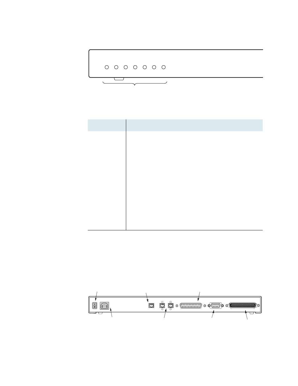
Figure 1–4. 7000 Family IAD Front Panel
Rear Panel Connectors
On the rear panel, the IAD contains several connectors. The WAN
connectors vary by IAD—both are present, but one has a permanently
attached metal shield to prevent use.
Figure 1–5. 7000 Family IAD Back Panel
Table 1–2.
Front Panel LEDs
LED
Description
POWER
Illuminates when the IAD is powered on.
LAN LINK
Illuminates when there is an operational LAN connection
on the Ethernet port.
LAN ACT
Flashes when there is activity on the Ethernet port.
WAN LINK
Flashes as the IAD is establishing a link, and illuminates
solid when there is a proper connection on the DSL WAN
port and synchronization has been achieved.
VOICE
Illuminates when there is activity on the voice ports.
When connected to a Jetstream Voice Gateway, it
remains lit, and blinks when there is activity.
DCE LINK
Illuminates when there is a link between the IAD and
data communications equipment (DCE).
DCE ACT
Illuminates or blinks when there is activity on the DCE
link.
POWER
LAN
LINK
LAN
ACT
WAN
LINK
VOICE
Status Indicators
NetEngine 7200
Front Panel
DCE
LINK
DCE
ACT
WAN
Modules
RJ-45 or RJ-48C Jack
Telephone Lines
RJ-21X Jack
100-120 / 200-240 V
2.0A MAX. 50/60Hz
Console Line
DB-9
Ethernet
RJ-45 Jack
On/Off
Switch
AC Power
Input
Universal Serial
Interface (DB-25)
AC POWER INPUT
10/100 LAN
SDSL
CONSOLE
RS-232
VOICE LINES
DCE
V.35 / RS-530
T1