Verilink PRISM 3001 (34-00186) Product Manual User Manual
Page 32
3-2
O
PERATION
4
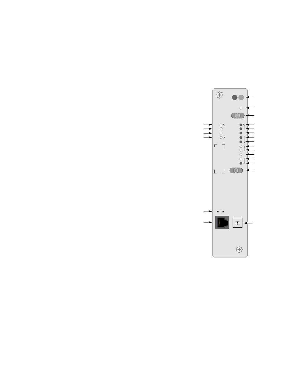
RTS: This green LED lights when the request to send signal is active.
5
DTR: This green LED lights when the data terminal ready signal is active.
6
Activity Indicators: These two small, recessed LEDs indicate supervisory and
network manager port activity.
Alarm Controls
and Indicators
7
ACO: This yellow LED lights whenever the
alarm cut off switch is placed in the left on
position. It indicates that the alarm relay contacts
are disabled.
8
ACO SW: The alarm cut off switch controls the
alarm relay circuitry. If the switch is placed in the
left on position, this circuitry is deactivated.
9
BV /CR / FE: This LED lights one second for
each second that has an occurrence of bipolar
violations (BPV), cyclic redundancy check
(CRC) errors, or frame bit errors (FBE).
10
LOS/OOF: This LED blinks with a loss of signal
(LOS) from the network. It lights constantly
when an out of frame (OOF) condition is
detected.
11
AIS: This alarm indication signal LED lights if
an unframed all ones condition is detected from
the network.
12
REM ALM: This LED lights constantly when a
remote (yellow) alarm signal is received.
13
LOC ALM: This LED lights when a local alarm
exceeding alarm thresholds exists.
Refer to Alarm Parameters in Alarm Parameters on page 4 -17 for more
information on alarm thresholds.
Test Controls
and Indicators
14
LLB: This LED lights continuously when the network interface is in a line
loopback. It flashes when the T1 DTE interface is in a line loopback. With PLB,
this LED also lights continuously when the unit is in NET MLB or flashes when
the unit is in DTE MLB.
STATUS
ACO SW
BV/CR/FE
LOS/OOF
AIS
REM ALM
LOC ALM
S
U
P
V
ACO
N
E
T
T
S
T
LOC
FAR
TD
RD
RTS
DTR
LLB
PLB
FLB
TST
ERR
PAT SEL
0
1
2
3
4
5 6
7
9
8
D
T
E
V.35
1
7
8
9
10
19
11
12
13
14
16
17
18
15
20
21
6
2
3
4
5
Figure 3-1 3001 Front Panel