Address switch s5 -5 configuration switch s6 -5 – Verilink PRISM 3001 (34-00186) Product Manual User Manual
Page 19
Unit Configuration
2-5
If the Alternate channel mode is selected, channel assignments are made with an
idle channel following each data channel. For the above example, data would be
carried on channels 1, 3, 5, and 7 and channels 2, 4, 6, and 8 would be set idle (set
to binary code 01111111). The advantage of alternate channel assignment is that
T1 ones density requirements are maintained by the idle channels rather that
placing any restrictions on the high-speed data.
Down: Contiguous
Up: Alternate
Address
Switch S5
Switch S5 is used to set the unit address. When using the EM8000 Element
Manager, 8100A Site Controller, or other network manager controlled products
with the 3001, each element in a group must have a unique unit address. Up to 250
units (with addresses from 1 to 250) can exist in a group. If the unit is not
connected to a network manager, the NMS unit address should be left at the
factory default setting of 1.
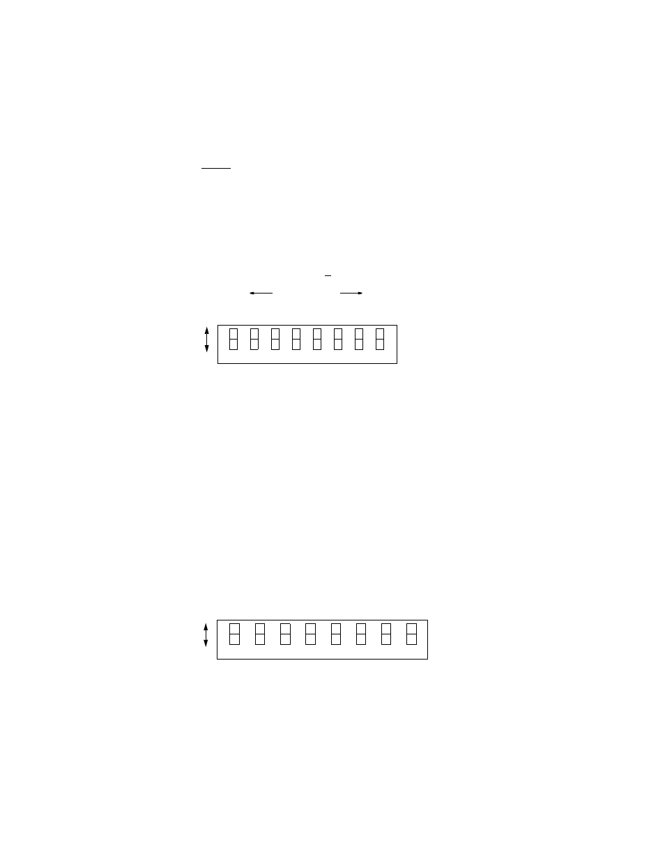
Switch S5 has 8 positions used to create an 8 -bit binary code for an address in the
range of 1 to 252. Switch position S5-1 is the least significant bit (LSB) and S5- 8
is the most significant bit (MSB). If a switch is down, its value is 0 and if it is up,
its value is that of the upper location. The values are additive. For example, to set a
unit address to five (5), position S5-3 (binary value = 4) and position S5-1 (binary
value = 1) would be set Up for a unit address of 5 (4 + 1). All other positions
would be set down.
Configuration
Switch S6
Switch S6 is used to set the configuration parameters listed in the following
paragraphs.
7
6
5
4
3
2
1
8
LSB
MSB
Binary values
Dn
Up
1
2
4
8
16
32
64 128
0
0
0
0
0
0
0
0
Figure 2-3 Switch S5
7
6
5
4
3
2
1
D
n
U
p
8
NM
S
SU
PV
Rate
Rate
NM
S
Rate
SU
PV
Rate
Bo
o
t
Mo
de
Bo
o
t
Mo
de
M
u
lt
ipli
e
r
Not use
d
Figure 2-4 Switch S6