Connecting the cims, Connecting the cims -4, Figure 2-2, “rear view of cim interconnections – Verilink APS 2000 T1 Line Protection (880-502411-001) Product Manual User Manual
Page 28: Eqpt, Figure 2-2 rear view of cim interconnections
Quick Setup
2-4
Verilink APS 2000 User Manual
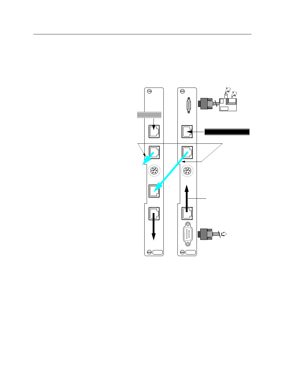
Connecting the CIMs
After installing the CSUs into the shelves, connect each module to
the external customer premise equipment. These connections are
made at the associated CIM 2022 APS or CIM 2010 APS in back of
the shelf.
Figure 2-2 Rear view of CIM interconnections
Ethernet adapter
9-pin
To
(10BaseT and 10Base2
connector
REV *
EQ
P
T
E
T
HE
RNE
T
EX
T T
IM
IN
G
SL
IP
NE
T
W
ORK
CIM
2022
REV *
EQ
PT
EX
T T
IM
IN
G
N
E
T
W
O
R
K
CIM
2010
SLIP connection
Ethernet
T1 Protection Line (P1)
T1 Line (L2)
Slot 1
Slot 2
connections)
Installing the Protection Line (Slot 1):
1.
Plug the T1 protection line (P1) into the
Network Port of the CIM 2022 APS in Slot
1.
2.
Run an RJ-48 cable from the
EQPT
Port of
the CIM 2022 APS to its APS IN port.
3.
Connect the APS CIMs in your shelf by
cabling the APS OUT port on the Slot 1
CIM to the APS IN port on the next APS
CIM. Continue daisy-chaining APS OUT
ports to APS IN ports for all the TACs on
your shelf. Leave the APS OUT port on the
lowest priority CIM empty.
NOTE: Both ends of the T1 protection group
must have the same priority cabling
sequence.
Making the network management connections
1.
Use
Management Port (IN) for SLIP con-
nection.
2.
Use the
Management Extension
port for
Ethernet connection.
3.
Use the Craft interface to configure IP
addresses.
To
SLIP peer
AP
S
OUT
AP
S
I
N
A
PS O
U
T
APS
APS
APS priority
cables
To Low Priority CPE
part numbe
458-502572-001