2 receiver – Thinklogical StudioPRO Extender Manual User Manual
Page 15
®
S t u d i o P R O E x t e n d e r P r o d u c t M a n u a l , R e v . D , O c t o b e r , 2 0 1 3
Page 14
3.7.2
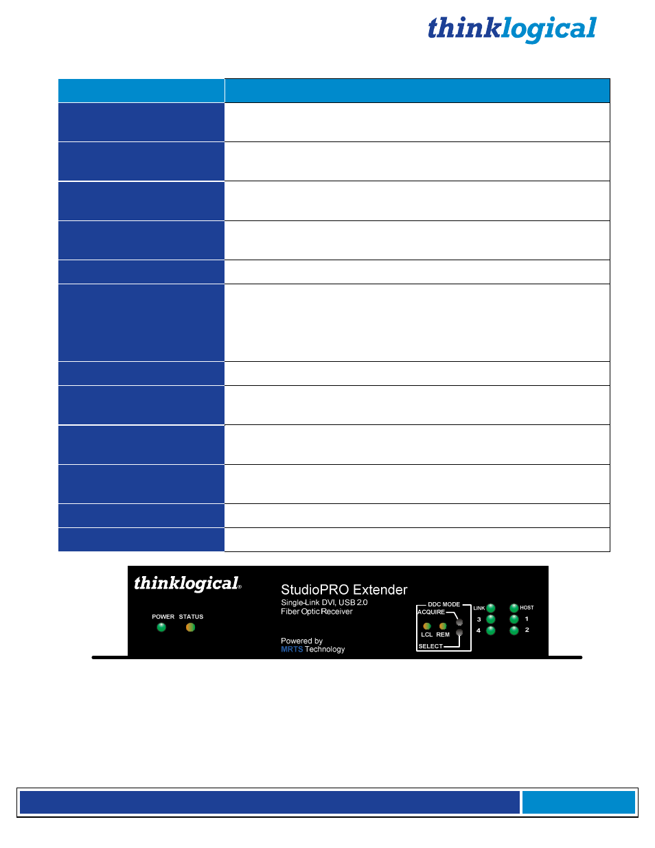
Receiver
Indicator LEDs
Status
DDC MODE: Pass-Thru
Local LED is GREEN
&
Remote LED is GREEN:
Acts as a direct
connection between CPU and display. No emulation is performed.
DDC MODE: Remote
Dynamic
Local LED is OFF
&
Remote LED is Green:
EDID is read from the
remote display and is updated each time the remote display changes.
DDC MODE: Remote Static
Local LED is ORANGE
&
Remote LED is Green:
EDID is read from
the remote display when the acquire button is pressed.
DDC MODE: Local Static
Local LED is GREEN
&
Remote LED is ORANGE:
EDID is read from
the local display when the acquire button is pressed.
POWER
GREEN LED is ON
when power is connected.
LINK
Shows the status of connections:
GREEN LED is ON
when the Power, device port(s), and Fibers are
properly connected.
GREEN LED is BLINKING
when the fibers are properly connected and
while the Host is enumerating.
HOST
GREEN LED is ON
when the computer establishes a USB connection.
1, 2, 3, 4
GREEN LED is ON:
Indicates an established connection to USB-A
Port 1, 2, 3 and/or 4.
RX Status LED
(Near the Power LED)
The status LED indicates the connection status of the RX Extender.
GREEN:
Good Link and DVI monitor connected to primary port (port on left
looking at DVI connectors).
ORANGE:
No DVI monitor connected to primary port.
RED Flashing:
No Fiber Link from TX to RX (L1 is not connected).