Figure 35: root dsp sub-system, Smt6040, Sundance simulink toolbox – Sundance SMT6040 User Manual
Page 42
Sundance Multiprocessor Technology Limited
Form : QCF32
SMT6040
“Sundance Simulink Toolbox”
Date : 6 July 2006
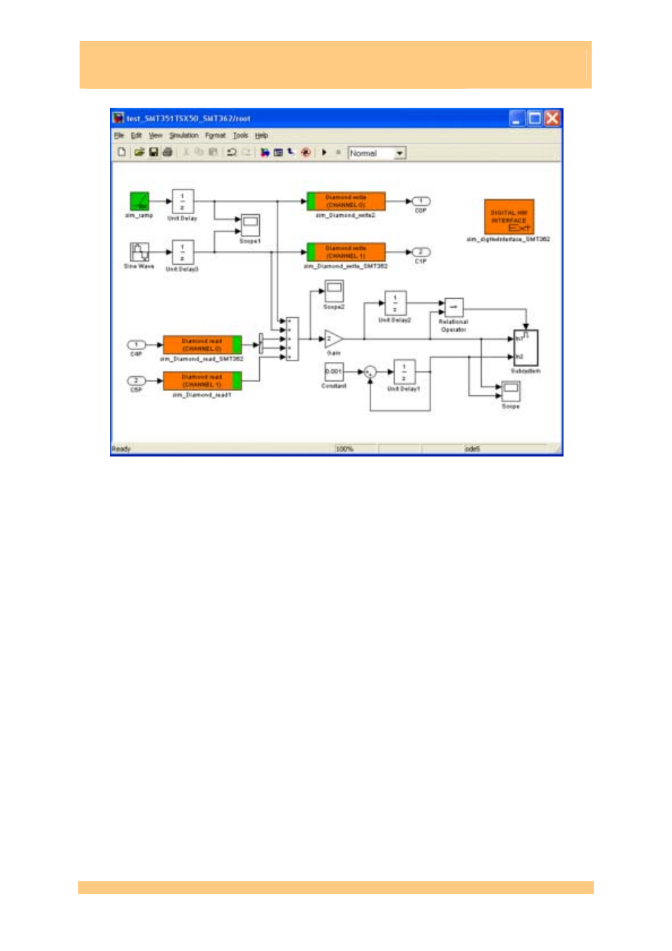
Figure 35: root DSP sub-system
The sim_digHwInterface block represents the Sundance carrier board (generally a
SMT310Q, but, thanks to Sundance modularity, this same demo can be run on a SMT148-FX
carrier without changing any SMT6040 parameters – only the wires will need to be re-
defined in case different hardware links are in place).
Each processor is associated with a sim_system block, whose name will automatically be
given to the corresponding Diamond nodes or FPGA configuration file. It is important that
one of the DSPs on the board located on TIM1 of the carrier is given the name root. All the
others may have any valid name (alphanumeric characters, no blank).
Inside each DSP (that is, inside each sim_system) there is a SMT6040 model of the
algorithm that shall be placed onto that DSP. For instance, in node root (double-click on
block root) there is the sub-system pictured in Figure 35.
This shows how to use Diamond channels and how to process the data received by another
processor.
Where the sim_digHwInterface block represents one of the two DSPs of the SMT362
board, so it is configured as in Figure 36. Please notice that the scrolldown menu allows
selecting the target board among several Sundance boards, so users can configure the
application to target their hardware.
SMT6040 - “Sundance Simulink Toolbox”
Last Edited: 08/01/2010 15.42
Page 42 of 53