Smithy CNC Mills User Manual
Page 99
SmithyCNC Programmer’s Reference Manual: Tool File & Compensation 9-17
Line 15 contains G41 D4, which means that the diameter of the tool described
as tool #4 in the tool table will be used to offset the spindle by 1/2 the diame-
ter, which is, of course, the tool's radius. Note that the line with the G41 com-
mand contains the endpoint of the move where the radius compensation is
interpolated in. What this means is that at the beginning of this move, there is
no compensation in effect, and at the end, the tool is offset by 100% of the
selected tool radius. Immediately after the G41 is D4, meaning that the offset is
by the radius of tool number 4 in the tool table. Note that tool DIAMETERS are
entered in the tool table. (Jon's tool diameter is about 0.4890)
But, note that in line 110, where the G40 'cancel cutter compensation' command
is, that cutter compensation will be interpolated out in this move. The way I
have these set up, the moves in lines 15 and 110 are almost exactly parallel to
the X axis, and the difference in Y coordinates is to line the tool up
outside the portion of the program where cutter compensation is in force.
Some other things to note are that the program starts with a G40, to turn off
any compensation that was in effect. This saves a lot of hassle when the pro-
gram stops due to a concavity error, but leaves the compensation turned on.
Also note in line 15 that G17 is used to select the XY plane for circular
interpolation. I have used the radius form of arc center specification rather than
the I,J form. EMC is very picky about the radius it computes from I,J coordi-
nates, and they must match at the beginning and end of the move to within
10^-11 internal units, so you will have lots of problems with arbitrary arcs.
Usually, if you do an arc of 90 degrees, centered at (1.0,1.0) with a radius of 1",
everything will go fine, but if it has a radius that can not be expressed exactly in
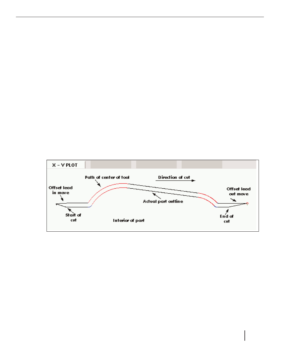
Figure 9-9 Cutter Compensation