Sloan MCR 4004-A CONTROLLER User Manual
Page 3
Combination: Used to control combination fixtures.
1. I/O-1 used to control a hot water.
2. I/O-2 used to control a cold water.
3. I/O-3 used to
control a closet.**
4. I/O-4 used to control a shower
1. Carefully remove protective paper from both sides of plastic
cover, taking care not to damage reset switch.
2. Positioning the cover so that reset switch in on right-hand
side, connect RJ-11 connector of reset switch into
connection in control box (located directly below 24 VAC
terminal connection).
1. Turn on power to controller.
2. Wait for LED 17 and LED 18 to stop flashing.
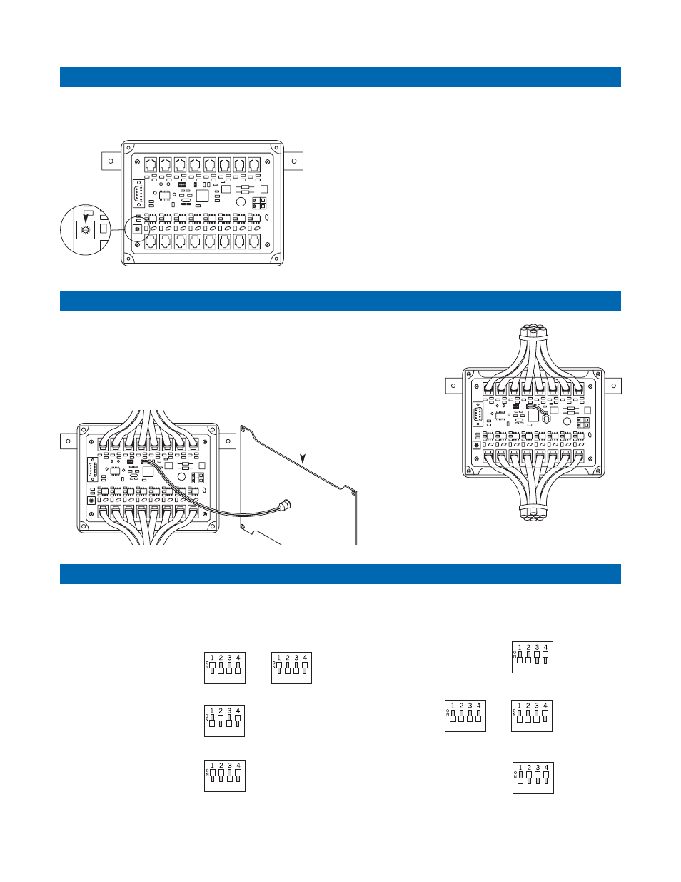
Step 4 — Adjusting the Potentiometer
Step 5 — Reinstall Plastic Cover/Connect Reset Button
Application Settings for MCR 4004-A Controller
3. Carefully position plastic cover onto
box so that all push button cables
are going through
opening at top
of box and all
solenoid cables
are going through
opening at bottom
of box.
4. Insert cover screws
and tighten.
The MCR 4004-A controller can be configured for different
applications including all closet, all shower, all lavatories and
combination by setting an on-board 4-position dip switch.
All Closets: Used to control
up to 4 water closets.*
All Showers: Used to control
up to 4 single runtime showers.
All Lavatories: Used to control
up to 4 single runtime
water lavatories.
2 in 5 min.
3 in 15 min.
All Showers
All Lavatories
Combination
I/O-1 Hot water and
I/O-2 Cold water
“Run Time” adjusting
I/O-3 Closet
w/Elec. Flushometer
Lockout Time
adjusting
I/O-4 Shower
“Run Time” adjusting
Potentiometer
PLASTIC COVER
* On water closets only, first dip switch in ON position activates random delay flushing.
In OFF position, random delay flushing is deactivated.
Note: the dip switches are factory set in the OFF position which equals an all closet
(4) function – 2 flushes in 5 minutes with 1 hour lockout and no random delay.
3. Turn potentiometer to maximum counterclockwise setting.
This is zero position.
4. Slowly turn potentiometer clockwise. Count the
number of times that LED 18 flashes. Each flash relates to
a time increment that increases either a runtime or lockout
time. When adjusting runtime, each flash equals 30-seconds.
When adjusting a lockout, each flash equals 15-minutes.
5. Repeat steps 2-4 until LED flashes for appropriate timing
adjustment. Run times can be adjusted in 30-second
increments from a minimum of 30-seconds to a maximum
of 17-minutes. Lockout times can be adjusted in 15-minute
increments from 0 to a maximum of 225-minutes.
**Standard setting: via dip switch #4 in OFF position activates 2 flushes in 5 minutes
with a 60 second lockout for a third activation attempt within the 5 minute time frame.
Option: via dip switch #4 in ON position activates 3 flushes in 15 minutes with a
60 minute lockout time.