Step 3 — head and basin assembly, Step 4 — sensor connection, Step 5 — drain and water supply line connection – Sloan EWF-42000 Installaton User Manual
Page 4: Step 6 — supply power to lavatory system
4
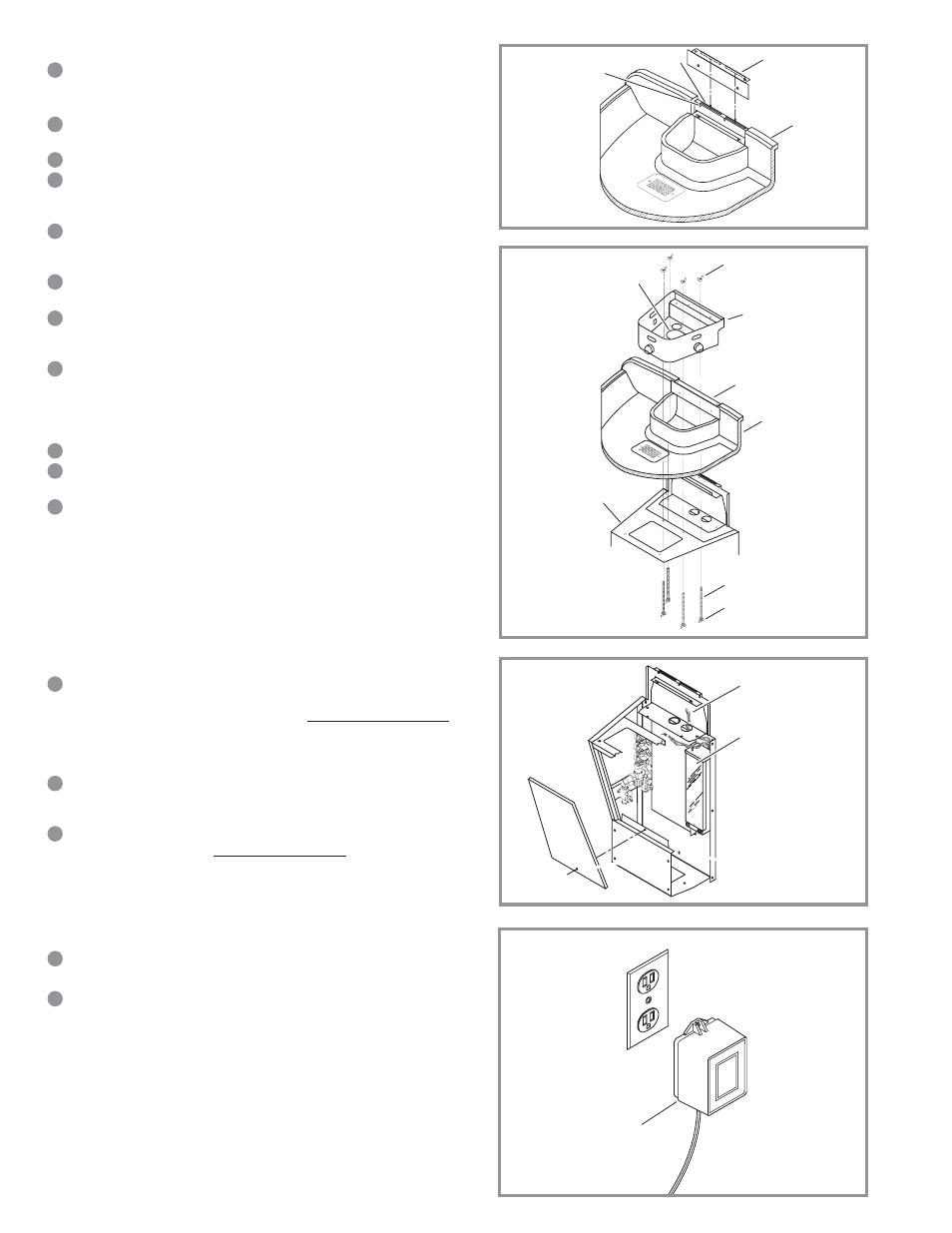
Step 3 — Head and Basin Assembly
With the help of an assistant, carefully lift Basin onto Pedestal.
Caution: Do not leave bowl on pedestal unsupported. It may fall and cause damage or
personal injury.
From beneath Basin, align the 4 (four) threaded brass inserts of Basin with the
2 (two) holes on Pedestal Top Plate and the 2 (two) holes on the Back Panel.
Secure with 4 (four) ¼-20 x ½” security screws (do not fully tighten screws).
Locate the Basin Bracket, and slide Tinnerman nuts over the top 2 (two) holes.
Find the tabs on the back of the Bracket. Slide tabs into the slots on the top of
the Back Panel.
Swing the Basin Bracket down so that it holds the Basin firmly in place.
(Note: The basin bracket is designed to fit tightly so that it pulls the basin firmly
against the wall.)
Using 2 (two) security screws, secure Basin Bracket in place. Tighten screws
referred to in Step “C” (tighten back two screws first, then front two screws).
Locate the Actuator Housing Assembly and the 2 (two) remaining Rubber
Grommets. Turn the Actuator Housing Assembly over and insert a Rubber
Grommet into each of the 1¾” diameter holes.
Turn the Actuator Housing Assembly back over and set it on top of the Basin.
Position it so that the 2 (two) holes near the back of the Actuator Housing
Assembly line up with the 2 (two) holes on top of the Basin Bracket. Using 2
(two) ¼-20 x ½” security screws, secure in place (do not fully tighten
screws).
Locate the 4 (four) 6” Threaded Rods and 8 (eight) ¼-20 Wing Nuts.
Thread one Wing Nut onto each Threaded Rod, just until the threads come
through the other side.
Place 1 (one) Threaded Rod down through the large oblong Access Hole in the
center of the Actuator Housing Assembly. Feed the Threaded Rod back up
through one of the 4 (four) holes on the Pedestal Top Panel and through the
corresponding hole in the Actuator Housing Assembly. Thread a Wing Nut onto
the end of the Threaded Rod and tighten securely. Repeat the process for the
other holes. Tighten the 2 (two) screws referred to in Step “H.”
Step 4 — Sensor Connection
Locate the group of colored wires tagged “upper” coming from the top of the
Electrical Enclosure. Feed that group of wires up through the middle of the
Basin and into the Actuator Housing Assembly through the Right Grommets.
Note: Use wire tie mounts and wire ties to route and secure wiring. Wires are long enough
to accommodate various routing paths. Longer wires may need to be bundled with wire ties
so they do not come in contact with sharp corners.
Plug like-colored wires into each Sensor; e.g., two red wires to one Sensor,
two orange wires to another Sensor, etc. Like-colored wires can be connected
to either connector of the same Sensor.
Locate the 3/8” x 4’ colored Tubing Water Lines and run them up into the
Actuator Housing Assembly through the Left Grommets. Match the color of
Tubing and Wire for each station; e.g., Red Wires are connected to one
Sensor, and the Red colored Tubing must be connected to that Sensor’s Spray
Head. Loosen the Plastic Nut of each Spray Head and firmly push the Tubing
into the appropriate Straight Connectors. Tighten Nuts securely.
Step 5 — Drain and Water Supply Line Connection
Install P-trap and drain lines making sure all connections are secure.
Note: P-trap and drain lines furnished by others.
Flush supply line(s) of any debris. Install Flex Hose(s) to water supply line(s).
Tighten fitting(s) securely
Step 6 — Supply Power to Lavatory System
Make sure that power is supplied to the receptacle. Once all wiring within the system
is connected, plug the Transformer into the receptacle.
Important: Plug-in Transformer MUST be used with a Ground Fault Interrupt (GFCI) Receptacle to
help prevent possible electrical shock.
BASIN
WALL MOUNTING HOLE
ACTUATOR
HOUSING
ASSEMBLY
BACK PANEL
BASIN BRACKET
BASIN BRACKET
ACCESS HOLE
WING NUTS
WING NUTS
THREADED RODS
PEDESTAL TOP PANEL
ELECTRICAL ENCLOSURE
WIRES TAGGED “UPPER”
GO TO ACTUATOR
HOUSING ASSEMBLY
ETF-233
PLUG-IN
TRANSFORMER
BASIN
A
B
C
D
E
F
G
H
I
J
K
A
B
C
A
B