Sloan EWF-42000 Installaton User Manual
Page 3
3
INSTALLATION INSTRUCTIONS
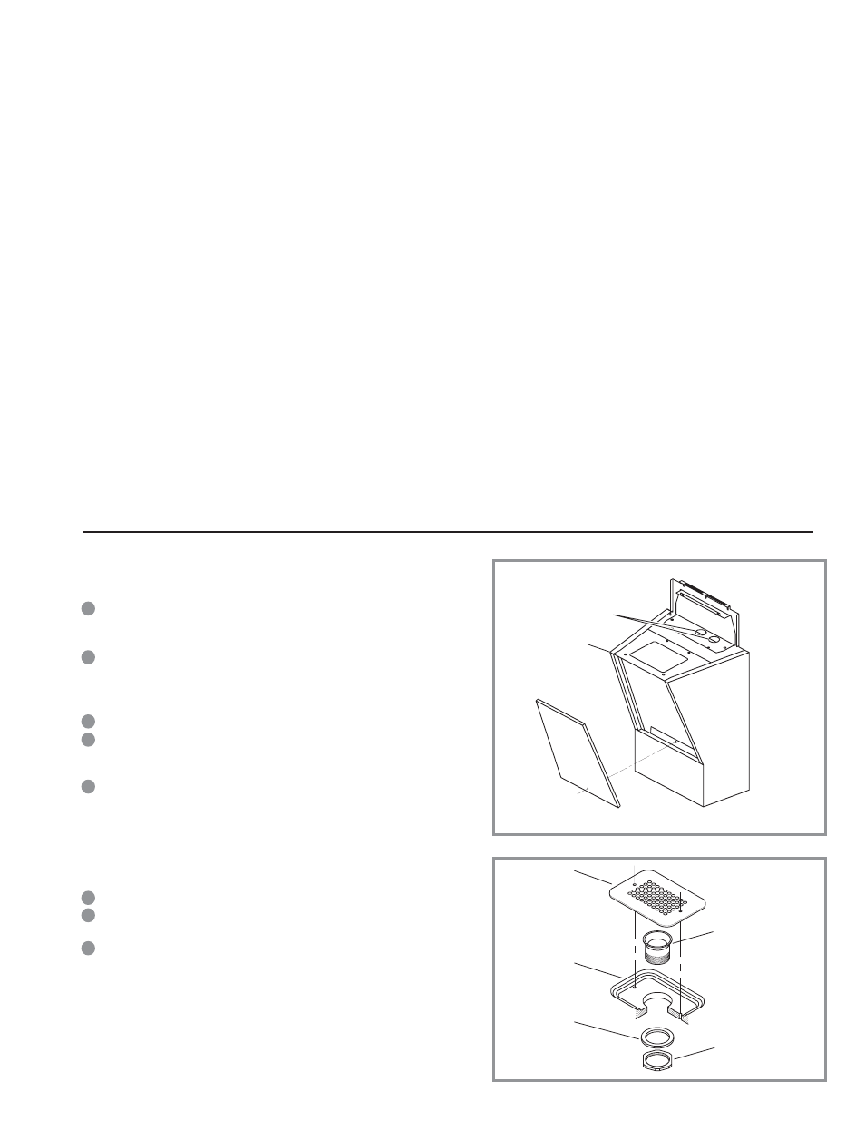
Step 1 — Pedestal Mounting
Measure and mark the centerline of the Washfountain on the wall and floor.
Note: For off-the-floor units, mark a level horizontal line at 36½” above the finished floor
for a rim height of 34”.
Place Back Panel against wall and align the three middle mounting holes with
the centerline marked on wall. Back Panel must be level and plumb against the
wall so that water in Basin will drain correctly once assembly is completed.
Note: For off-the-floor units, align top of pedestal with the horizontal line.
Drill holes in wall at all mounting hole locations on the back panel.
Secure Pedestal to wall using bolts, washers and wall anchors that are suitable
for your specific type of wall: drywall, concrete, metal studs, wood studs, etc.
(Wall anchors supplied by installer.)
Once Pedestal is secured to the wall, locate the 2 (two) Rubber Grommets
(supplied) and insert them into the 2 (two) 1¾” diameter holes located on top
of Pedestal.
PRIOR TO INSTALLATION
Prior to installing the Sloan Optima EWF-40000 Series Lavatory System, install the
items listed below. Also, refer to the appropriate rough-in diagram on Page 2.
• Plug-IIn TTransformer — Install electrical receptacle(s) for plug-in transformer(s)
— 120 VAC, 2 amp service for each ETF-233 (24 VAC, 35 VA) plug-in transformer
used.
• Hot and cold water supply lines or tempered water supply line
• Drain line
Important:
• ADEQUATE STRUCTURAL SUPPORT IN OR BEHIND THE WALL IS REQUIRED.
REFER TO THE APPROPRIATE ROUGH-IN DIAGRAM ON PAGE 2 FOR DRY WEIGHT
OF SINK. STRUCTURAL SUPPORT MUST HAVE A MINIMUM PULLOUT RATING OF
1000 POUNDS (450 Kg).
• ALL ELECTRICAL WIRING SHOULD BE INSTALLED IN ACCORDANCE WITH
NATIONAL/LOCAL CODES AND REGULATIONS.
• ALL PLUMBING SHOULD BE INSTALLED IN ACCORDANCE WITH APPLICABLE
CODES AND REGULATIONS.
• A 24 VAC STEP-DOWN TRANSFORMER MUST BE USED FOR HARDWIRE
APPLICATIONS.
• DO NOT PLUG TRANSFORMER INTO POWER SOURCE (RECEPTACLE) UNTIL ALL
WIRING IS COMPLETED. PERMANENT DAMAGE TO THE TRANSFORMER AND
CIRCUIT CONTROL MODULE WILL RESULT IF 24 VAC WIRES TOUCH
EACH OTHER OR SHORT WHEN POWER SUPPLY IS ACTIVE.
• BEFORE CONNECTING FLEX HOSES TO SUPPLY STOPS, FLUSH ALL
WATER LINES UNTIL WATER IS CLEAR.
TOOLS REQUIRED FOR INSTALLATION
• Electric drill for drilling anchor holes.
• Socket or open end wrench for installing anchoring fasteners.
• Open end wrench for connecting water lines.
• Pipe wrench for installing drain line.
SINK LOCATION
Determine the appropriate wall location for the Lavatory System. Consider
that hot and cold water supply lines, a drain line, and an electrical source
(receptacle) will be required. Compare the physical dimensions of the
Lavatory System to the space available for the installation. If wall is not
load bearing, a carrier may be required behind the wall. Refer to the
appropriate Rough-in diagram on Page 2 for Lavatory System dimensions.
Prior to Lavatory System installation, electric wiring, plumbing supply and
drain must be installed.
A
Step 2 — Strainer Installation
Insert Drain Spud into Basin using plumbers putty (supplied by installer).
From beneath Basin, install the Washer and Locknut onto the Drain Spud and
secure Locknut against Basin.
Install Strainer using the 2 (two) #10-24 x ½” flat Phillips-head screws
supplied.
STRAINER
DRAIN SPUD
LOCKNUT
WASHER
BASIN
RUBBER GROMMETS
PEDESTAL
B
C
D
E
A
B
C