Install transformer (continued), Mount control module to wall – Sloan ETF-500 Faucet User Manual
Page 5
5
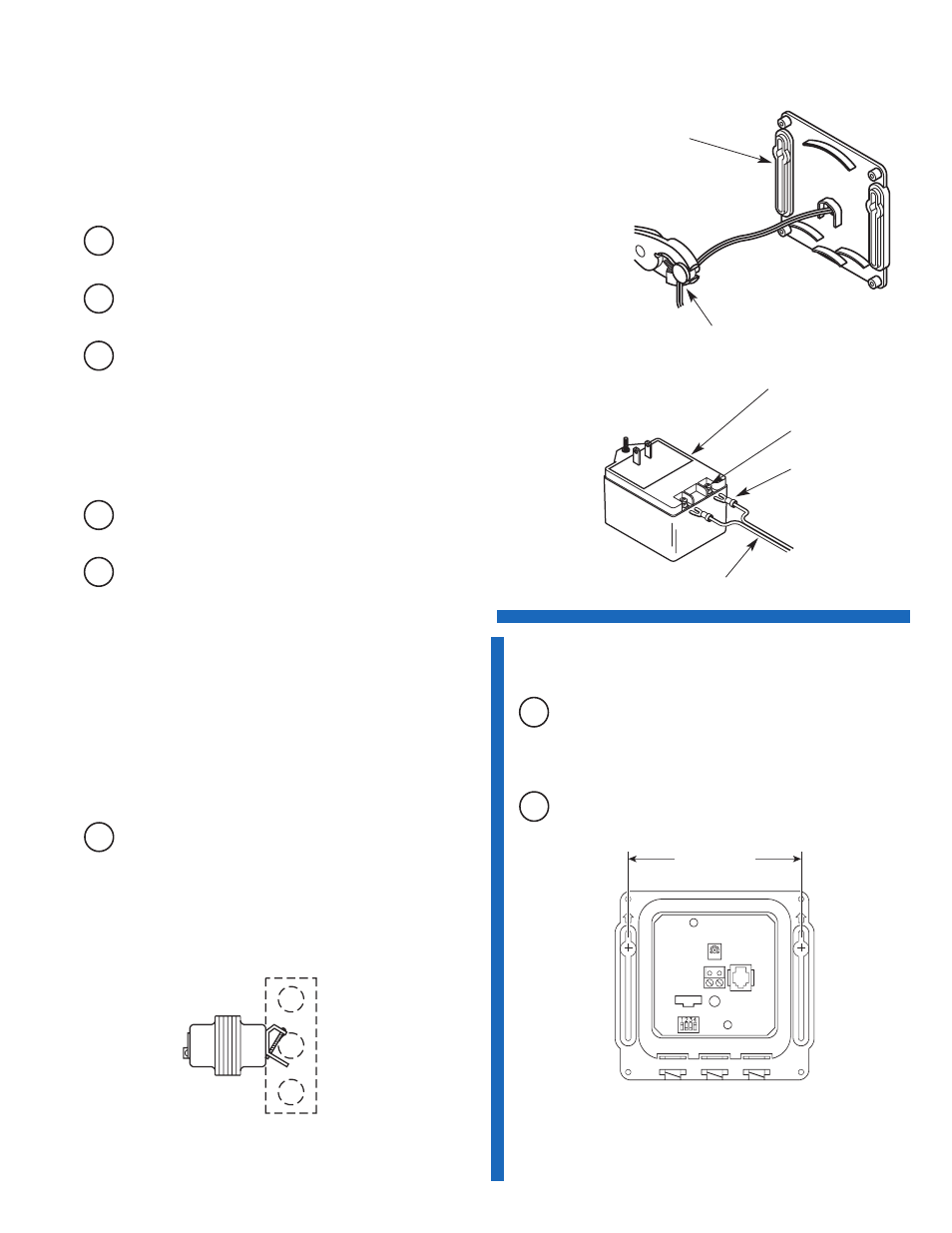
Box Mount Transformers
Important: DO NOT supply power to primary side of Transformer until
all wiring has been completed.
Mount Transformer on a metal electrical junction box (supplied by
others). (“J” box should be mounted inside chase wall or above
ceiling.) Install Transformer within 50 feet (15.24 meters) of Faucet.
18 gauge wire is recommended.
A
Run wires from secondary side of Transformer to 3/8 inch
(10 mm) hole at back of Control Module Enclosure. If
necessary, wires can be run through wall and then inserted
through hole in back of Control Module Enclosure.
Plug-in Transformers
Important: DO NOT plug Transformer into receptacle until all wiring has
been completed.
The Transformer is supplied with a 10 foot Cable; however, this Cable
can and should be shortened to meet installation requirements.
A
Strip ends of Transformer Power Cable approximately 3/16 to
1/4 inch (5 to 6 mm).
B
Install Strain Relief 3 inches (76 mm) from one end of Power
Cable.
Important: Twist stranded ends of Power Cable before inserting into
Terminal Block. Fraying of Stranded Power Cable Wire can cause a
short and damage the Control Module and Transformer when powered.
E
Install Crimp Connectors and connect Power Cable ends to
Transformer Terminals.
120 VAC
PRIMARY
24 VAC
SECONDARY
BOX MOUNT
TRANSFORMER
(EL-248-40 SHOWN)
PLUG-IN TRANSFORMER
TRANSFORMER
TERMINALS
CRIMP CONNECTORS
POWER CABLE
PLUG-IN
TRANSFORMER
(ETF-233 SHOWN)
CONTROL
MODULE
BASE
STRAIN RELIEF
D
Connect Power Cable to Terminal Block on Connector Board.
See Step 6.
C
Insert Power Cable and Strain Relief into hole at back of
Control Module. Install right angle Strain Relief so that Power
Cable enters the Control Module from the bottom.
4
Install Transformer (Continued)
5
Mount Control Module to Wall
A
Install the Control Module in an appropriate location as shown in
Rough-in. Control Module must be installed so that all cables
enter from the bottom of the unit. When installed, Cables from the
Spout and Solenoid Valve to the Control Module should have
some slack.
B
Mount Control Module to wall using Mounting Screws and Plastic
Anchors.
EXTENSION CABLES
Extension Cables are available as an option from Sloan to allow
for installing the Control Module remote from the Faucet Spout
and Solenoid Valve. Refer to the Parts List for available lengths.
4” (102 mm)