Sloan ETF-600 Faucet User Manual
Page 5
5
A
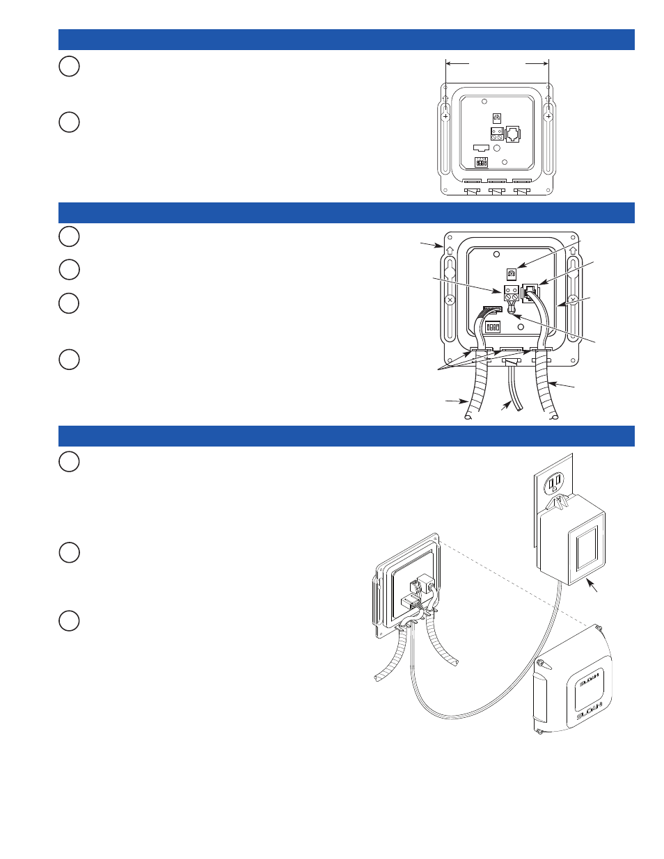
Install the Control Module in an appropriate location as shown in
Rough-in. Control Module must be installed so that all cables enter
from the bottom of the unit. When installed, Cables from the Spout
and Solenoid Valve to the Control Module should have some slack.
A
Route Cables from Solenoid Valve and Spout to the Control Module.
C
Insert Locking Connector from Faucet Spout into mating
Receptacle on Connector Board. Allow 3 to 4 inches (76 to 102
mm) of Cable to extend into the Control Module.
B
Mount Control Module to wall using Mounting Screws and Plastic
Anchors.
EXTENSION CABLES
Extension Cables are available as an option from Sloan to allow for
installing the Control Module remote from the Faucet Spout and Solenoid
Valve. Refer to the Parts List for available lengths.
4” (102 mm)
CONTROL
MODULE
ENCLOSURE
FROM SOLENOID
VALVE
FROM TRANSFORMER
STRAIN RELIEF SLOTS
FROM FAUCET SPOUT
TERMINAL BLOCK -
1. REMOVE TERMINAL
BLOCK
2. INSERT POWER
CABLES
3. SECURE WITH
SCREWS
4. REINSTALL
TERMINAL BLOCK
CONNECTOR
BOARD
POWER
CABLE
MODULAR
RECEPTACLE
B
Insert Solenoid Valve Connector into the Modular Receptacle on
Connector Board.
D
Insert each Conduit Cable into a strain relief slot in the Control
Module.
A
Plug Transformer into 120 VAC Receptacle.
Note: The Control Module is equipped with two LED lights. When power is
supplied by the Transformer, one LED will illuminate green. When Sensor is
activated, this LED will change to red. A second red LED illuminates when
Solenoid Valve is activated.
B
Open Supply Stop(s). With Aerator removed, activate Faucet for 30
seconds by placing hands in front of Sensor. The Solenoid Valve
should “click” and water should flow from the Spout. If this does
not occur, refer to the Troubleshooting section of this instruction
instructions.
C
Close Supply Stop(s) and install Spray Head in Spout using the Key
provided. Reopen Supply Stop(s), activate Faucet and check for
leaks.
TRANSFORMER
5 - MOUNT CONTROL MODULE TO WALL
6 - CONNECT CONTROL MODULE CONNECTIONS
7 - PLUG IN TRANSFORMER AND START-UP
RANGE ADJ.
SCREW –
SEE STEP 8