Install valve module wall bracket, Connect flex hose or copper tubing to spout – Sloan EBF-187 Faucet User Manual
Page 3
3
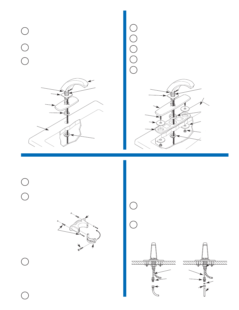
1B
ETF-312-A (for EBF-187) Single
Hole 4” Trim Plate
A
Slide Rubber Faucet Gasket onto Faucet Shank. Ensure that Roll
Pin on base of Faucet fits into hole in Rubber Faucet Gasket.
B
Slide Trim Plate and Back-up Spacer onto Faucet Shank. Align Roll
Pin with small slot in Trim Plate.
C
Secure Faucet from below Deck using the Flange Nut supplied.
ROLL PIN
RUBBER FAUCET
GASKET
TRIM PLATE
BACK-UP
SPACER
DECK
FAUCET SHANK
FLANGE NUT
1C
ETF-510-A (for EBF-85/187) Single
Hole 8” Trim Plate
A
Slide Rubber Faucet Gasket onto Faucet Shank. Ensure that Roll
Pin on base of Faucet fits into hole in Rubber Faucet Gasket.
B
Slide Trim Plate and Back-up Spacer onto Faucet Shank. Align Roll
Pin with small slot in Trim Plate.
C
Slide Washer Gaskets over Studs. Place Studs and Faucet Shank
through Base Gasket and holes in Deck.
D
Secure Trim Plate from below Deck using the two (2) Fender
Washers and two (2) Finger Nuts supplied.
E
Secure Faucet from below Deck using the Flange Nut supplied.
ROLL PIN
RUBBER
FAUCET
GASKET
TRIM PLATE
STUD
DECK
FAUCET SHANK
WASHER
GASKET (2)
BASE
GASKET
BACK-UP
SPACER
FENDER
WASHER (2)
FINGER NUT (2)
FLANGE NUT
EBF-187 FAUCET
2
Install Valve Module Wall Bracket
A
Install the Wall Bracket in an appropriate location as shown in the
Rough-In illustrations on Page 2.
WALL
BRACKET
BASE
WALL
BRACKET
SELF-TAPPING SCREW
PLASTIC ANCHOR
WITH SCREW AND
WASHER SHOWN
B
Position Wall Bracket within 20 inches (508 mm) from Faucet.
When installed, the Fiber Optic Cable from the Faucet Spout to the
Valve Module should have some slack.
C
Use Wall Bracket Base as a template to mark off holes on wall for
Mounting Screws. Determine the appropriate Mounting Fastener
for the particular wall type (three different fastener types are
included; see parts list). Drill two (2) appropriately sized holes:
For Plastic Wall Anchor — 1/4” (6 mm) holes
For Hollow Wall Anchor — 5/16” (8 mm) holes
For Toggle Nut Anchor — 3/8” (10 mm) holes
3
Connect Flex Hose or Copper
Tubing to Spout
A
Install the 1/4 inch end of the 1/4 to 3/8 inch Compression Fitting
onto the Spout’s copper Supply Tube.
IMPORTANT: Keep thread sealant out of your waterway to prevent
component part damage! DO NOT use any sealant on compression
fittings. For threaded pipe fittings, DO NOT apply sealant to the first
two "starter" threads.
B
Connect one end of Flex Hose or Copper Tube to the Compression
Fitting.
COPPER
SUPPLY TUBE
1/4 TO 3/8 INCH
COMPRESSION
FITTING
FLEX HOSE
3/8” (10 mm)
COPPER
SUPPLY TUBE
FLEX HOSE
CONNECTION
COPPER TUBE
CONNECTION
FERRULE
COMPRESSION
NUT
D
Install Wall Bracket Base to wall using the appropriate fastener.