Sloan 952 Royal Concealed 900 Hydraulic Series User Manual
Page 6
6
D
Slide plastic tubing into its corresponding valve actuator fitting. Pull
tubing to make sure connection is secure. (Tubing can be removed
by pressing on blue connection button to release.)
Cut off excess tubing with plastic tube cutter (PTC) so that there
will be about 3” to 4” (76 to 102 mm) of slack when connected to
valve actuator. If “L” and “O” markings on the tubing will be cut
off, then remark tubing appropriately to retain identification.
C
Observe “L” and “O” markings on Tubing. Tubing must be connected
to corresponding “L” and “O” markings on Valve Actuator.
NOTE
A
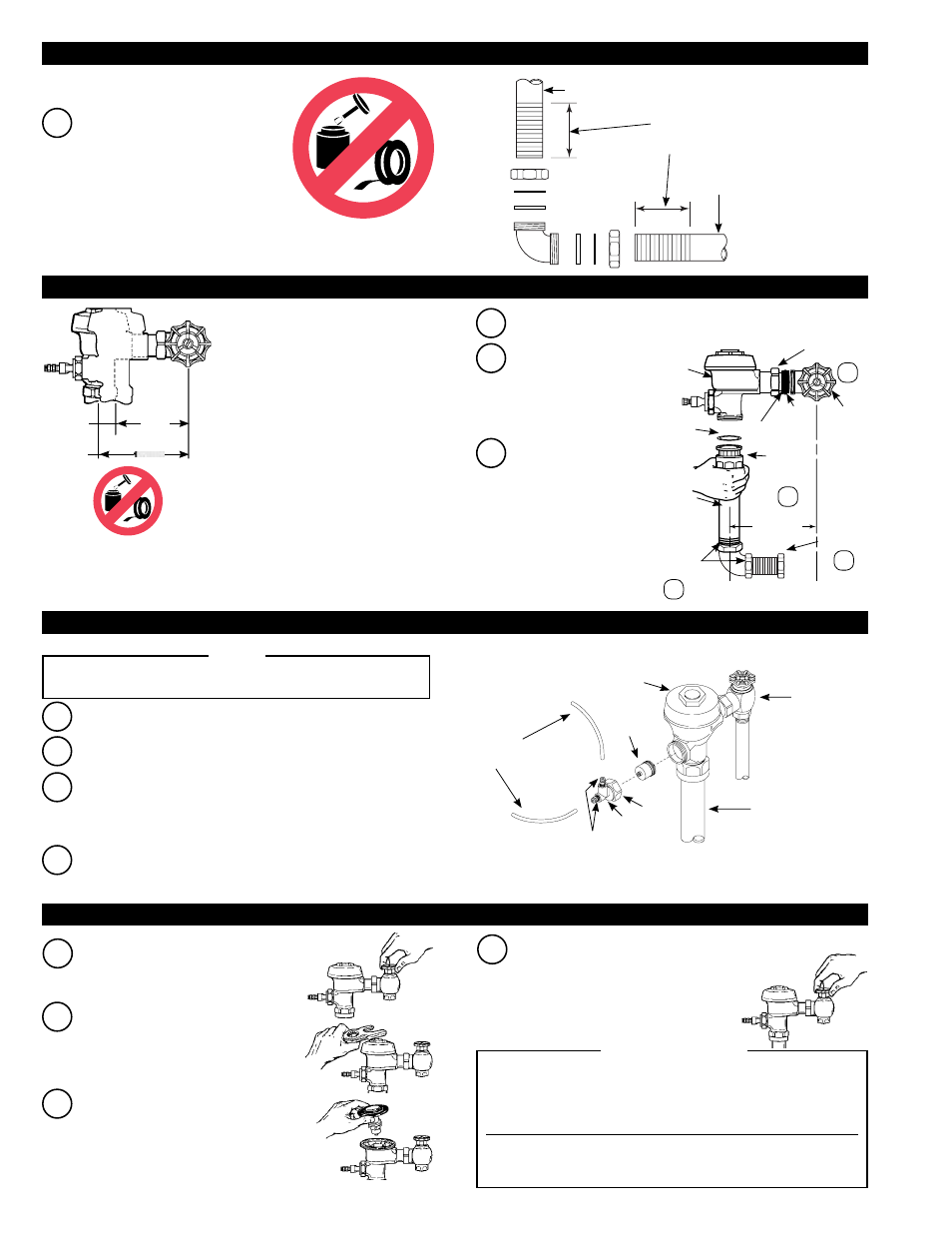
Assemble Pipe, Elbows, Couplings,
Nylon Slip Gaskets, Rubber Gaskets
and Flanges as illustrated on back
page. Hand tighten all Couplings.
Align Flushometer
Body on top of
Vacuum Breaker
Flush Connection.
Hand tighten Vacuum
Breaker Coupling.
B
C
Align Flushometer
Body. Using a wrench,
securely tighten
couplings in order
given: (1) Tailpiece
Coupling, (2) Vacuum
Breaker Coupling, (3)
Slip Joint Couplings
and (4) Spud Coupling.
A
Insert Adjustable Tailpiece into Control Stop. Lubricate O-ring seal
with water. Hand tighten Tailpiece Coupling.
4-1/4”
(108 mm)
5-1/4”
(133 mm)
MIN.
MAX.
Maximum adjustment of Sloan Adjustable
Tailpiece is 1/2” (13 mm) IN or OUT from
the standard 4-3/4” (121 mm) (centerline
of Flushometer to centerline of Control
Stop). If rough-in measurement exceeds
5-1/4” (133 mm), consult factory for longer
tailpiece.
IMPORTANT: Use a Sloan A-50 Super-
Wrench™, Sloan A-109 Plier Wrench
or smooth jawed spud wrench to secure
all couplings. This will eliminate damage
to chrome or special finish that normally
occurs when slip-joint pliers, pipe wrenches
or other “toothed” tools are used.
IMPORTANT: WHEN CUTTING SCORED PIPE TO
FIT, LEAVE A MINIMUM OF 1-1/4” (32 mm) OF
SCORING TO ENSURE PROPER ENGAGEMENT
WITH COMPRESSION COUPLINGS.
VACUUM BREAKER
FLUSH
CONNECTION
C/L
SUPPLY
C/L
FIXTURE
4-3/4”
(121 mm)
VACUUM
BREAKER
COUPLING
SPUD
COUPLING
FLUSHOMETER
BODY
VACUUM
BREAKER
FLUSH
CONNECTION
WITH
REPAIR KIT
SLIP JOINT
COUPLINGS
CONTROL
STOP
TAILPIECE
COUPLING
ADJUSTABLE
TAILPIECE
O-RING
1
3
2
4
G-44
FRICTION
RING
B
Install valve actuator housing onto flushometer valve body.
Tighten housing nut with a wrench.
Insert actuator cartridge into flushometer valve body.
A
BAK-CHEK
®
CONTROL STOP
FLUSHOMETER VALVE BODY
HY-83-A
ACTUATOR
CARTRIDGE
VALVE
ACTUATOR
HOUSING
QUICK CONNECT
FITTINGS (2)
PLASTIC
TUBING
VACUUM
BREAKER
TUBE
HOUSING
NUT
SLOAN FLUSHOMETERS ARE ENGINEERED FOR QUIET OPERATION. EXCESSIVE
WATER FLOW CREATES NOISE, WHILE TOO LITTLE WATER FLOW MAY NOT
SATISFY THE NEEDS OF THE FIXTURE. PROPER ADjUSTMENT IS MADE
WHEN THE PLUMBING FIXTURE IS CLEANSED AFTER EACH FLUSH WITHOUT
SPLASHING WATER OUT FROM THE LIP AND A QUIET FLUSHING CYCLE IS
ACHIEVED.
NEVER OPEN CONTROL STOP TO WHERE THE FLOW FROM THE VALVE
EXCEEDS THE FLOW CAPABILITY OF THE FIXTURE. IN THE EVENT OF A VALVE
FAILURE, THE FIXTURE MUST BE ABLE TO ACCOMMODATE A CONTINUOUS
FLOW FROM THE VALVE.
!!! IMPORTANT !!!
Shut off control stop by turning handle
CLOCKWISE. Then remove flushometer
cover.
A
Lift out the inside parts assembly as
a complete unit. Reinstall flushometer
cover and tighten with wrench. Open
control stop. Turn on water supply to
flush line of any debris or sediment.
B
C
Shut off control stop and remove
flushometer cover. Reinstall Inside parts
assembly and flushometer cover. Tighten
cover with wrench. Open control stop and
activate flushometer Valve.
Adjust control stop to meet flow rate
required for proper cleansing of fixture.
Open control stop COUNTERCLOCKWISE
ONE FULL turn from closed position.
Activate flushometer. Adjust control stop
after each flush until the rate of flow
delivered properly cleanses the fixture.
D
3 - INSTALL VACUUM BREAKER FLUSH CONNECTION
4 - INSTALL FLUSHOMETER
5 - INSTALL VALVE ACTUATOR
6 - FLUSH OUT SUPPLY LINE AND ADjUST CONTROL STOP