Sloan 952 Royal Concealed 900 Hydraulic Series User Manual
Page 5
5
(1) The push button actuator is connected to the flushometer
body by two plastic tubes, marked “L” and “O”. Match
markings on the tubes to markings on the actuator.
(2) Cut off excess plastic tubing with plastic tube cutter (PTC)
leaving 3” to 4” (76 to 102 mm) of slack when push button
actuator is installed. If the “L” and “O” markings will be cut
off, remark the tubing to not lose identification.
(3) Slide plastic tubing into its corresponding valve actuator
fitting. Pull tubing to make sure connection is secure.
(Tubing can be removed by pressing on blue connection
button to release.)
STEPS TO ATTACH PLASTIC TUBING
Using cover plate as a template, drill two 3/16” (5 mm) Cover plate
mounting holes and cut opening for push button actuator into the
metal partition. Install clip nuts with threaded side toward back.
A
Insert threaded end of Push Button Actuator through Cover Plate
and wall flange and install Nut. Tighten Nut securely.
B
Attach Plastic Tubing. See: Steps to Attach Plastic Tubing (lower
right side of page).
C
Insert flathead screws through wall flange and cover plate
mounting holes. Mount wall flange and cover plate to metal
partition using flathead screws provided. Tighten fasteners
securely.
D
Place brass Insert into black Push Button. Concave side of Brass
Insert must face outward of Push Button.
E
Insert black push button into Button Flange. Place Spring against
Brass Insert of Push Button. Install Push Button Assembly onto
Wall Flange. Secure with Setscrew located on Button Flange.
F
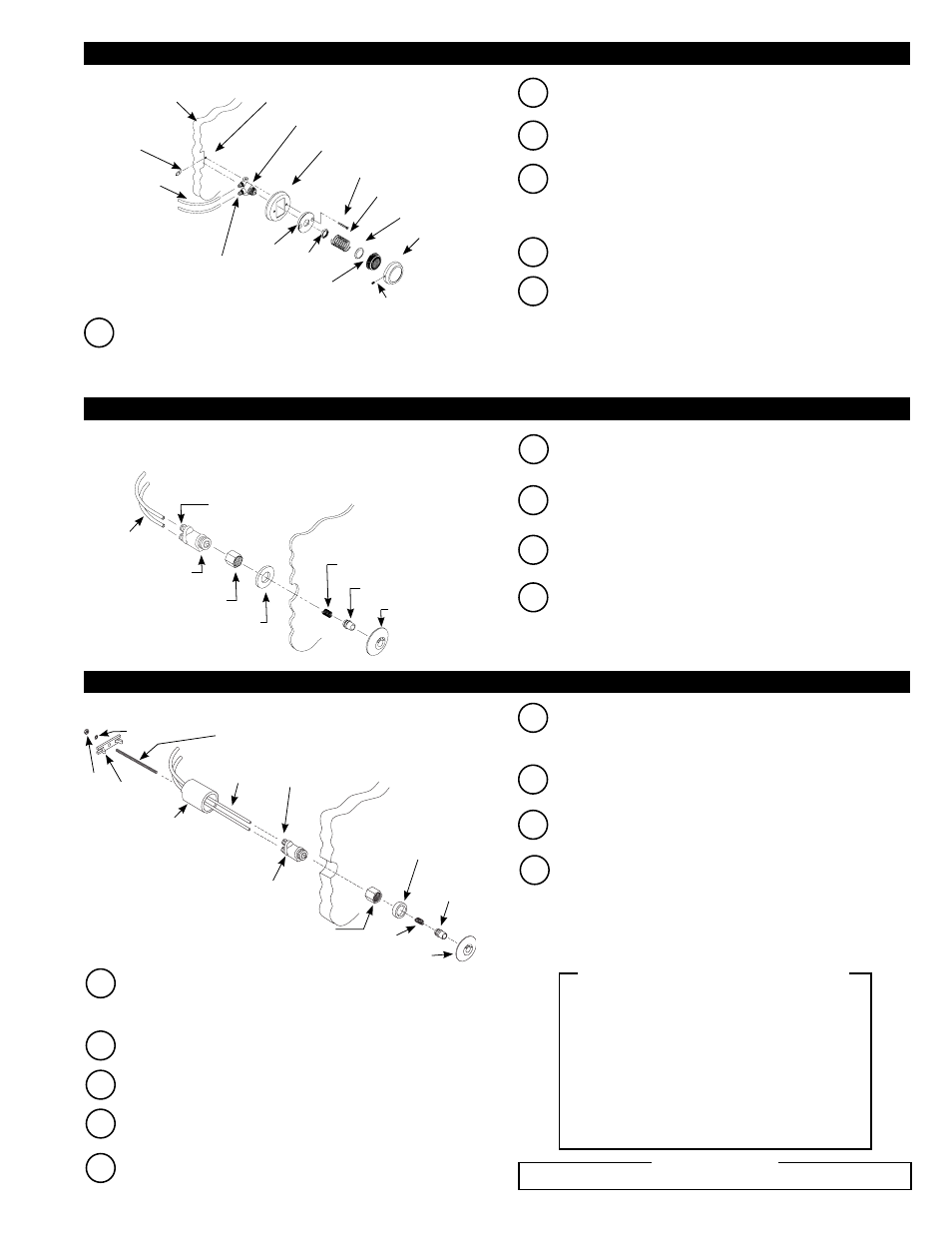
2D - INSTALL HY-49-A METAL PARTITION (MP VARIATION) PUSH BUTTON ACTUATOR
2F - INSTALL HY-100-A METAL BUTTON – FIXTURE WALL (MBFW VARIATION)
2E - INSTALL HY-108-A METAL BUTTON – PANEL MOUNT (MBPM VARIATION)
Note: Behind wall access required to install HY-100-A (MBFW)
Note: Use HY-108-A (MBPM) on punched stainless steel plates
and security fixtures with front access.
Attach Plastic Tubing to Push Button Actuator. See: Steps to Attach
Plastic Tubing (below).
A
B
Thread Actuator Assembly Nut onto threaded end of Push Button
Actuator.
C
Slide Spring over Metal Push Button until it snaps into place.
Insert Metal Push Button into Button Flange.
D
From front of panel, insert Button Flange Assembly into hole of
panel. Behind panel, place Washer over threads of Button Flange.
Thread Button Flange onto Actuator. Tighten Flange securely.
BUTTON FLANGE
METAL BUTTON
SPRING
PANEL
WASHER
ACTUATOR
ASSEMBLY NUT
PUSH BUTTON
ACTUATOR
QUICK
CONNECT
FITTINGS (2)
PLASTIC
TUBING
PUSH BUTTON
SPRING
NUT
WALL
FLANGE
PUSH BUTTON ACTUATOR
QUICK
CONNECT
FITTINGS (2)
COVER PLATE
MOUNTING HOLE
CLIP
NUTS (2)
METAL
PARTITION
BUTTON
FLANGE
SETSCREW
FLATHEAD SCREWS (2)
COVER PLATE
BRASS INSERT
PLASTIC
TUBING
B
Screw Threaded Rod into back of Push Button Actuator.
If not already completed, bore a 1-1/2” (38 mm) diameter hole in
wall for the Push Button Actuator. Refer to the Rough-in drawings
on Pages 1 and 2.
A
C
Thread Actuator Assembly Nut onto end of Push Button Actuator.
D
Slide Spring over Metal Push Button until it snaps into place.
Insert Metal Push Button into Button Flange.
E
Place Spacer Ring over threads of Button Flange and thread
Button Flange Assembly into Actuator Assembly Nut.
F
From behind wall, run plastic tubing through optional spacer sleeve
(notched end of sleeve toward rear) and wall. Spacer sleeve only
required if wall thickness is less than 2” (51 mm).
G
Attach plastic tubing. See: Steps to Attach Plastic Tubing (below).
H
Insert push button assembly into the 1-1/2” (38 mm) wall hole.
I
From behind wall, slide spacer sleeve (if required) over threaded
rod and rest it against rear of wall. Slide retaining bar onto
threaded rod and into slots of sleeve (if required), or against wall
if sleeve is not required. Install lockwasher and nut onto threaded
rod. Tighten securely. Carefully cut excess threaded rod, making
certain to not damage plastic tubing.
BUTTON FLANGE
METAL
BUTTON
SPRING
SPACER
RING
ACTUATOR
ASSEMBLY
NUT
WALL
PUSH
BUTTON
ACTUATOR
QUICK
CONNECT
FITTINGS (2)
PLASTIC
TUBING
SPACER SLEEVE —
USE ONLY IF WALL
THICKNESS IS LESS
THAN 2” (51 mm)
THREADED ROD
LOCKWASHER
RETAINING
BAR
NUT
MUST USE SLOAN APPROVED TUBING ONLY
!!! IMPORTANT !!!