Sloan 110 Royal Exposed Flushometer User Manual
Page 4
1. Flushometer does not function (no flush).
A. Control stop or main valve is closed. Open control stop or main valve.
B. Handle assembly is damaged. Replace handle or install handle repair kit.
C. Relief Valve is damaged. Replace relief valve.
2. Volume of water is not sufficient to siphon fixture.
A. Control stop is not open wide enough. Adjust control stop for desired delivery of
water volume.
B. Diaphragm assembly is damaged. Replace diaphragm assembly.
C. Incorrect diaphragm assembly is installed in flushometer; for instance, urinal
assembly inside a closet flushometer, or low consumption assembly inside a
higher consumption fixture. Determine the flush volume required by the fixture and
replace diaphragm. Use valve label and markings on fixture for reference.
D. Water supply volume or pressure is inadequate. If no gauges are available to
properly measure supply pressure or volume of water at the flushometer, then
remove the relief valve from the diaphragm assembly, reassemble the flushometer
and completely open the control stop.
• If the fixture siphons, more water volume is required. Install a higher flushing
volume diaphragm.
IMPORTANT – LAWS AND REGULATIONS
PROHIBIT THE USE OF HIGHER FLUSHING VOLUMES
THAN LISTED ON FIXTURE OR FLUSHOMETER.
• If the fixture DOES NOT siphon or if a low consumption flush is required, steps
must be taken to increase the water supply pressure and/or volume. Contact the
fixture manufacturer for minimum water supply requirements of the fixture.
3. Length of flush is too short (short flush).
A. Diaphragm assembly is worn or damaged. Replace diaphragm assembly.
B. Handle assembly is damaged. Replace handle or install handle repair kit.
C. Incorrect diaphragm assembly is installed in flushometer; for instance, urinal
assembly inside a closet flushometer, or low consumption assembly inside a
higher consumption fixture. Determine the flush volume required by the fixture and
replace diaphragm. Use valve label and markings on fixture for reference.
4. Length of flush is too long (long flush) or continuous.
A. Metering bypass hole (upper filter ring) in diaphragm is clogged. Remove the
diaphragm assembly. Remove the primary and secondary filter rings from the
diaphragm, wash under running water, and reassemble. Replace as necessary.
B. Diaphragm or relief valve is damaged. Replace diaphragm or relief valve.
C. Incorrect diaphragm assembly is installed in flushometer; for instance, closet
assembly inside a urinal flushometer, or water saver assembly inside a low
consumption flushometer. Determine the flush volume required by the fixture and
replace the diaphragm. Use valve label and markings on fixture for reference.
D. Inside cover is damaged. Replace Inside cover.
E. Supply line water pressure has dropped and is not sufficient to close the valve.
close control stop until pressure is restored.
F. Relief valve is not seated properly. Disassemble diaphragm components
(relief valve, filter rings, and diaphragm unit), wash under running water, and
reassemble. Replace as necessary.
5. Chattering noise is heard during flush.
A. Inside cover is damaged. Replace inside cover.
B. Relief valve or diaphragm is damaged. Replace relief valve or diaphragm assembly.
6. Handle Leaks.
A. Handle seal or assembly is damaged. Replace handle or install handle repair kit.
7. Water splashes from fixture.
A. Control stop is open wider than necessary. Adjust control stop for desired delivery
of water volume.
B. Water saver/conventional diaphragm assembly is installed on low consumption
fixture or closit diaphragm assembly is installed on urinal fixture. Determine
the required flush volume (see label on valve or markings on fixture). Replace
diaphragm assembly or relief valve for appropriate flush volume of fixture.
When assistance is required, please contact your
local Sloan Representative or Sloan Technical Support at:
1-888-SLOAN-14 (1-888-756-2614)
DO NOT use abrasive or chemical cleaners (including chlorine bleach) to clean
Flushometers that may dull the luster and attack the chrome or special decorative finishes.
Use ONLY mild soap and water, then wipe dry with clean cloth or towel.
While cleaning the bathroom tile, protect the Flushometer from any splattering of cleaner.
Acids and cleaning fluids will discolor or remove chrome plating.
VANDAL RESISTANT CONTROL STOP CAP
REMOVAL
CARE AND CLEANING
TROUBLESHOOTING GUIDE
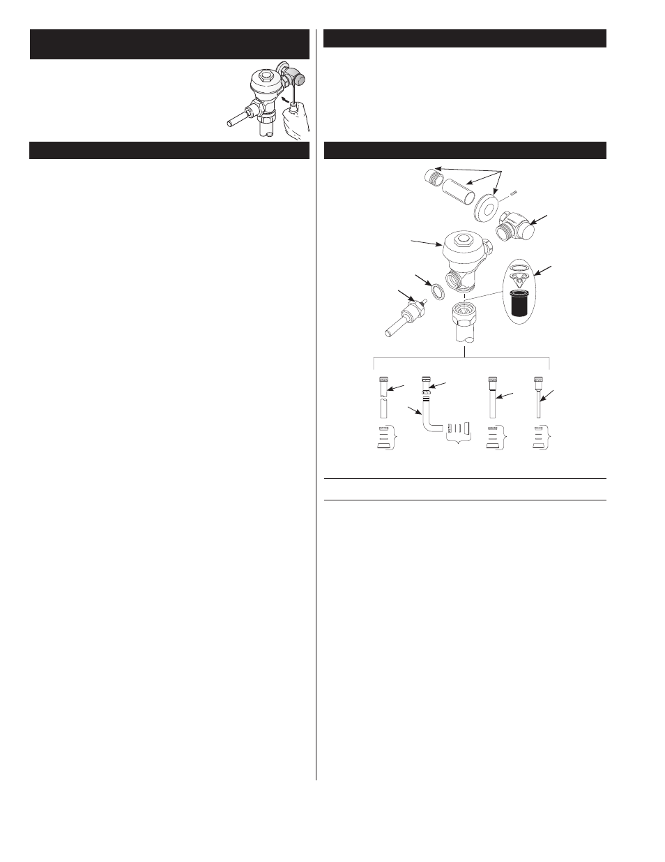
PARTS LIST
SLOAN • 10500 SEYMOUR AVENUE • FRANKLIN PARK, IL 60131
Phone: 1-800-982-5839 • Fax: 1-800-447-8329 • www.sloanvalve.com
© 2015 SLOAN VALVE COMPANY
Code No. 0816195 Rev. 6 (02/15)
H-
70
0
SE
RIE
S STOP
3
2
9
7
6A
6A
6B
6C
4A
4D
4B
4C
5
1A
8
Item Part
No. No.
Description
1
†
Valve Assembly
2
B-73-A
ADA Compliant Handle Assembly
3 H-700-A Bak-Chek
®
Control Stop
4A
V-600-AA 1½” (38 mm) Vacuum Breaker Assembly ‡
4B
V-600-AA 1¼” (32 mm) Vacuum Breaker Assembly
4C
V-600-AA ¾” (19 mm) Vacuum Breaker Assembly
4D
V-600-A
Vacuum Breaker Assembly
5
F-109
1½” (38 mm) Elbow Flush Connection
6A
F-56-A
1½” (38 mm) Spud Coupling Assembly
6B
F-57-A
1¼” (32 mm) Spud Coupling Assembly
6C
F-58-A
¾” (19 mm) Spud Coupling Assembly
7
H-634-AA 1” (25 mm) Sweat Solder Kit with Cast Set Screw Flange
H-636-AA ¾” (19 mm) Sweat Solder Kit with Cast Set Screw Flange
8
V-651-A
High Back Pressure Vacuum Breaker Repair Kit
9
A-31
Handle Gasket
†
Part number varies with valve model variation; consult factory.
‡
Length varies with valve model variation; consult factory.
NOTE:
The information contained in this document is subject to change without notice.
Use a large flat screwdriver as a lever to remove the Cap from
the Control Stop. Insert the screwdriver blade between the
bottom edge of the Cap and the flat surface of the Control
Stop body as shown. Push the screwdriver handle straight
back toward the wall to gently lift the Cap. If necessary, work
the screwdriver around the diameter of the Cap until you can
grasp the Cap and lift it completely off the Sleeve. The Sleeve
should remain attached to the bonnet of the Control Stop.
- 111 Royal Exposed Flushometer 113 Royal Exposed Flushometer 115 Royal Exposed Flushometer 116 Royal Exposed Flushometer 117 Royal Exposed Flushometer 180 Royal Exposed Flushometer 186 Royal Exposed Flushometer 120 Royal Exposed Flushometer 121 Royal Exposed Flushometer 122 Royal Exposed Flushometer 111 UPPERCUT Flushometer 113 UPPERCUT Flushometer 115 UPPERCUT Flushometer 116 UPPERCUT Flushometer 120 UPPERCUT Flushometer 601 Prison Flushometer 603 Prison Flushometer 611 Prison Flushometer 681 Prison Flushometer 609 Prison Flushometer 613 Prison Flushometer 9603 Prison Flushometer 9609 Prison Flushometer 9613 Prison Flushometer 110 Sloan Exposed Flushometer 111 Sloan Exposed Flushometer 113 Sloan Exposed Flushometer 115 Sloan Exposed Flushometer 116 Sloan Exposed Flushometer 117 Sloan Exposed Flushometer 180 Sloan Exposed Flushometer 186 Sloan Exposed Flushometer 120 Sloan Exposed Flushometer 121 Sloan Exposed Flushometer 122 Sloan Exposed Flushometer