Sloan 110 Regal Exposed Flushometer User Manual
Page 4
4
C
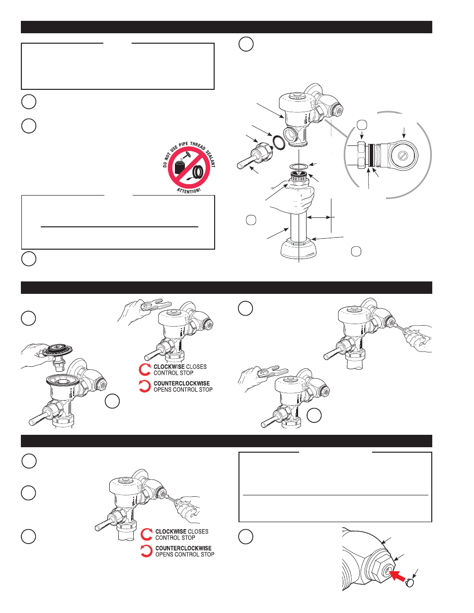
Align Flushometer Body. Using a wrench, securely tighten
couplings in the order given: (1) Tailpiece Coupling, (2) Vacuum
Breaker Coupling and (3) Spud Coupling.
B
Align Flushometer directly above the Vacuum Breaker Flush
Connection by sliding the Flushometer Body IN or OUT as needed.
Tighten Vacuum Breaker Coupling by hand.
A
Lubricate tailpiece O-ring with water. Insert Adjustable Tailpiece
into Control Stop. Tighten Tailpiece Coupling by hand.
Maximum adjustment of the Sloan Adjustable Tailpiece is 1/2”
(13 mm) IN or OUT from the standard 4-3/4” (121 mm) (centerline of
Flushometer to centerline of Control Stop).
If roughing-in measurement exceeds 5-1/4” (133 mm), consult
factory for longer tailpiece.
NOTE
TAILPIECE
COUPLING
CONTROL
STOP
1
FLUSHOMETER
BODY
VACUUM
BREAKER
COUPLING
2
ADJUSTABLE
TAILPIECE
O-RING
G-44
FRICTION
RING
SPUD
COUPLING
3
C/L
FIXTURE
C/L
SUPPLY
VACUUM
BREAKER
FLUSH
CONNECTION
4-3/4”
(121 mm)
±1/2”
(13 mm)
D
Install the red A-31 Handle Gasket on the Handle Assembly. Insert
the ADA Handle Assembly (B-73-A) into the Handle opening in the
Flushometer Body. Securely tighten the Handle coupling with a
wrench.
HANDLE
ASSEMBLY
HANDLE
COUPLING
A-31 GASKET
D
Install plug into the control
stop by pressing into bonnet.
A
Make sure Control Stop
is CLOSED and remove
Flushometer Outer Cover.
B
Remove Inside Cover and lift
out Inside Parts Assembly.
D
Reinstall Inside Parts Assembly, Inside
Cover and Outside Cover wrench tight.
H
-7
00
S
ER
IES
STOP
PLUG
BAK CHEK
®
CONTROL STOP
BONNET
Sloan’s flushometers are engineered for quiet operation.
Excessive water flow creates noise, while too little water flow
may not satisfy the needs of the fixture. Proper adjustment is
made when the plumbing fixture is cleansed after each flush
without splashing water out from the lip AND a quiet flushing
cycle is achieved.
Never open Control Stop to where the flow from the valve
exceeds the flow capability of the fixture. In the event of a
valve failure, the fixture must be able to accommodate a
continuous flow from the valve.
!!! IMPORTANT !!!
VACUUM
BREAKER
REPAIR KIT
B
Activate flushometer.
A
Open control stop COUNTERCLOCKWISE one FULL turn from
closed position.
C
Adjust control stop after
each flush until the rate
of flow delivered properly
cleanses the fixture.
Reinstall Outside and
Inside Cover wrench
tight. Open Control Stop
to flush supply line. Close
Control Stop and remove
Outside and Inside Cover.
C
3 - INSTALL FLUSHOMETER AND HANDLE ASSEMBLY
4 - FLUSH OUT SUPPLY LINE
5 - ADJUST CONTROL STOP AND INSTALL PLUG
For high efficiency urinal flushometers (0.5, 0.25 and 0.125 gpf),
it is necessary to first insert the flow control component into the
tailpiece assembly. See the H1015A flow control kit and separate
instructions for details on how to install.
NOTE