Sloan 110 Regal Exposed Flushometer User Manual
Page 3
3
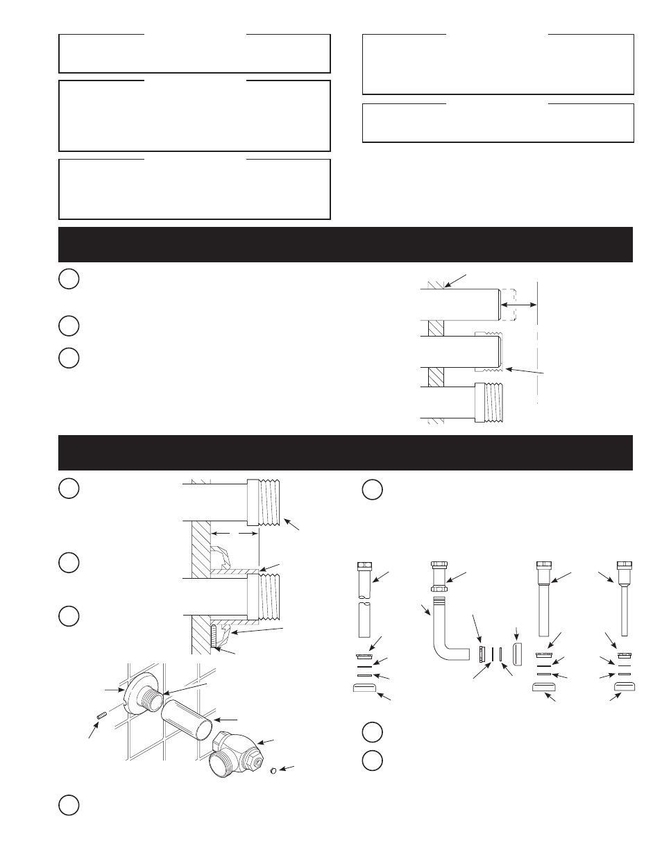
A
Measure from finished wall to C/L of Fixture Spud. Cut pipe 1¼”
(32 mm) shorter than this measurement. Chamfer O.D. and I.D. of
water supply pipe.
WATER SUPPLY PIPE
FINISHED WALL
1-1/4”
(32 mm)
C/L OF
FIXTURE
SPUD
SWEAT
SOLDER
ADAPTER
B
Slide Threaded Adapter fully onto pipe.
C
Sweat solder the Adapter to pipe.
WITH THE EXCEPTION OF CONTROL STOP INLET, DO
NOT USE PIPE SEALANT OR PLUMBING GREASE ON ANY
VALVE COMPONENT OR COUPLING!
!!! IMPORTANT !!!
PROTECT THE FINISH OF SLOAN’S FLUSHOMETERS —
DO NOT USE TOOTHED TOOLS TO INSTALL OR
SERVICE THESE VALVES. USE A SLOAN A-50 Super-
Wrench™, Sloan A-109 PLIER WRENCH OR SMOOTH
JAWED SPUD WRENCH TO SECURE ALL COUPLINGS.
SEE “CARE AND CLEANING” SECTION.
!!! IMPORTANT !!!
THIS PRODUCT CONTAINS MECHANICAL AND/OR
ELECTRICAL COMPONENTS THAT ARE SUBJECT TO
NORMAL WEAR. THESE COMPONENTS SHOULD BE
CHECKED ON A REGULAR BASIS AND REPLACED AS
NEEDED TO MAINTAIN THE VALVE’S PERFORMANCE.
!!! IMPORTANT !!!
Please take the time to read this manual to ensure proper product installation
and longevity. Also, please visit our website to download our most recent
documentation for this product.
If you have questions about how to install your Flushometer, consult your local
Sloan Representative or call Sloan Technical Support at:
1-888-SLOAN-14 (1-888-756-2614)
VACUUM
BREAKER
TUBE
SPUD COUPLING
NYLON SLIP
GASKET
RUBBER
GASKET
SPUD FLANGE
E
Slide spud coupling, nylon slip gasket, rubber gasket and spud
flange over vacuum breaker tube.
F
Insert Tube into Fixture Spud.
G
Hand tighten Spud Coupling onto Fixture Spud.
H
-7
00
S
ER
IES
STOP
BAK-CHEK
®
CONTROL STOP
COVER TUBE †
IRON PIPE NIPPLE OR
COPPER PIPE WITH
SWEAT SOLDER ADAPTER
SETSCREW †
SUPPLY
FLANGE
X
WATER
SUPPLY PIPE
SWEAT SOLDER
ADAPTER
COVER TUBE
WALL
FLANGE
SETSCREW
A
Measure from finished wall
to first thread of adapter
or threaded supply pipe
(dimension “X”). Cut cover
tube to this length.
B
Slide cover tube over pipe.
Slide wall flange over
cover tube until against
wall.
Thread Control Stop
onto pipe. Tighten with a
wrench making sure outlet
is positioned as required.
C
VACUUM
BREAKER
TUBE
SPUD COUPLING
NYLON SLIP
GASKET
RUBBER
GASKET
SPUD FLANGE
SPUD COUPLING
NYLON
SLIP
GASKET
RUBBER
GASKET
SPUD FLANGE
MODELS
110/111,
113, 115,
116 & 117
MODELS
120 & 122
MODEL
180
MODEL
186
Tighten setscrew with a 1/16” hex wrench.
DO NOT install
vandal resistant plug at this time.
D
ELBOW FLUSH
CONNECTION
NEVER OPEN CONTROL STOP TO WHERE THE FLOW
FROM THE VALVE EXCEEDS THE FLOW CAPABILITY
OF THE FIXTURE. IN THE EVENT OF A VALVE FAILURE,
THE FIXTURE MUST BE ABLE TO ACCOMMODATE A
CONTINUOUS FLOW FROM THE VALVE.
!!! IMPORTANT !!!
LAWS AND REGULATIONS PROHIBIT THE USE
OF HIGHER FLUSHING VOLUMES THAN LISTED ON
FIXTURE OR FLUSHOMETER.
!!! IMPORTANT !!!
VACUUM
BREAKER
PLUG
† COVER TUBE AND CAST SUPPLY FLANGE
WITH SETSCREW ARE AVAILABLE IN
“YBYC” SWEAT SOLDER KIT.
1 - INSTALL SWEAT SOLDER ADAPTER (ONLY IF YOUR SUPPLY PIPE DOES
NOT HAVE A MALE THREAD)
2 - INSTALL COVER TUBE, WALL FLANGE AND CONTROL STOP TO
SUPPLY PIPE AND INSTALL VACUUM BREAKER FLUSH CONNECTION