Seaward Sentinel User Manual
Page 10
ELECTRICAL SAFETY TESTER
USER MANUAL
13
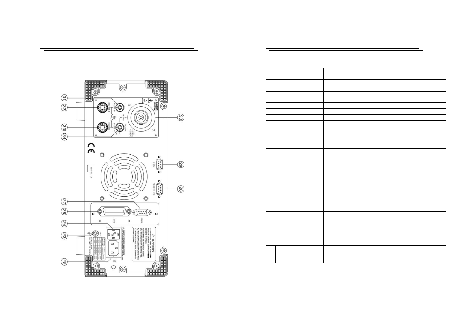
4-2. Rear Panel
ELECTRICAL SAFETY TESTER
USER MANUAL
14
1
Model Number
Model number and description
2
FAIL Indicator LED The red LED indicates failure of test procedure
3 PASS
Indicator
LED
The green LED indicates pass of test procedure
4 CAUTION
Indicator LED
During test the red LED will flash to indicate
dangerous.
5
Main Display LCD The LCD displays all message about test procedure.
6
START Button
Press the green button to start a test procedure.
7
RESET Button
Press the red button to reset/stop a test procedure.
8 MENU
Key
When you press the MENU key, the status becomes
MENU and you can browse all groups.
9 EDIT/SAVE
Key
When you press the EDIT/SAVE key, the status EDIT
is active and you can edit this step or setup. Press the
EDIT/SAVE key again will save this step or setup.
10 UTILITY Key
When you press the UTILITY key, the status
UTILITY is active and you can view all the utility
setups.
11 FIELD
Key
When you edit the test step, press the FIELD key to
change the active parameter of stop.
12 Left Arrow Key
Press the arrow key to adjust knob’s resolution.
13 Right Arrow Key
Press the arrow key to adjust knob’s resolution.
14 Knob
If status EDIT is active, turn the knob to increase or
decrease the value of active parameter.
If status MENU is active, turn the knob to increase or
decrease active Step.
15 LCD Backlight
Adjustment
Turn the VR to adjust the LED backlight of LCD.
16 Buzzer
Volume
Adjustment
Turn the VR to adjust the buzzer volume.
17 High
Voltage Output
Seat
High voltage output terminal.
18 SOURCE-Terminal
(only for Ground
Bond Test)
High current terminal for Ground Bond test.