Interface and input signal option, System setup and operations – RGBLink VSP 5162PRO User Manual
Page 77
6. System Setup and Operations
Interface and Input Signal Option
VSP 5162PRO User Manual 77
Interface and Input Signal Option
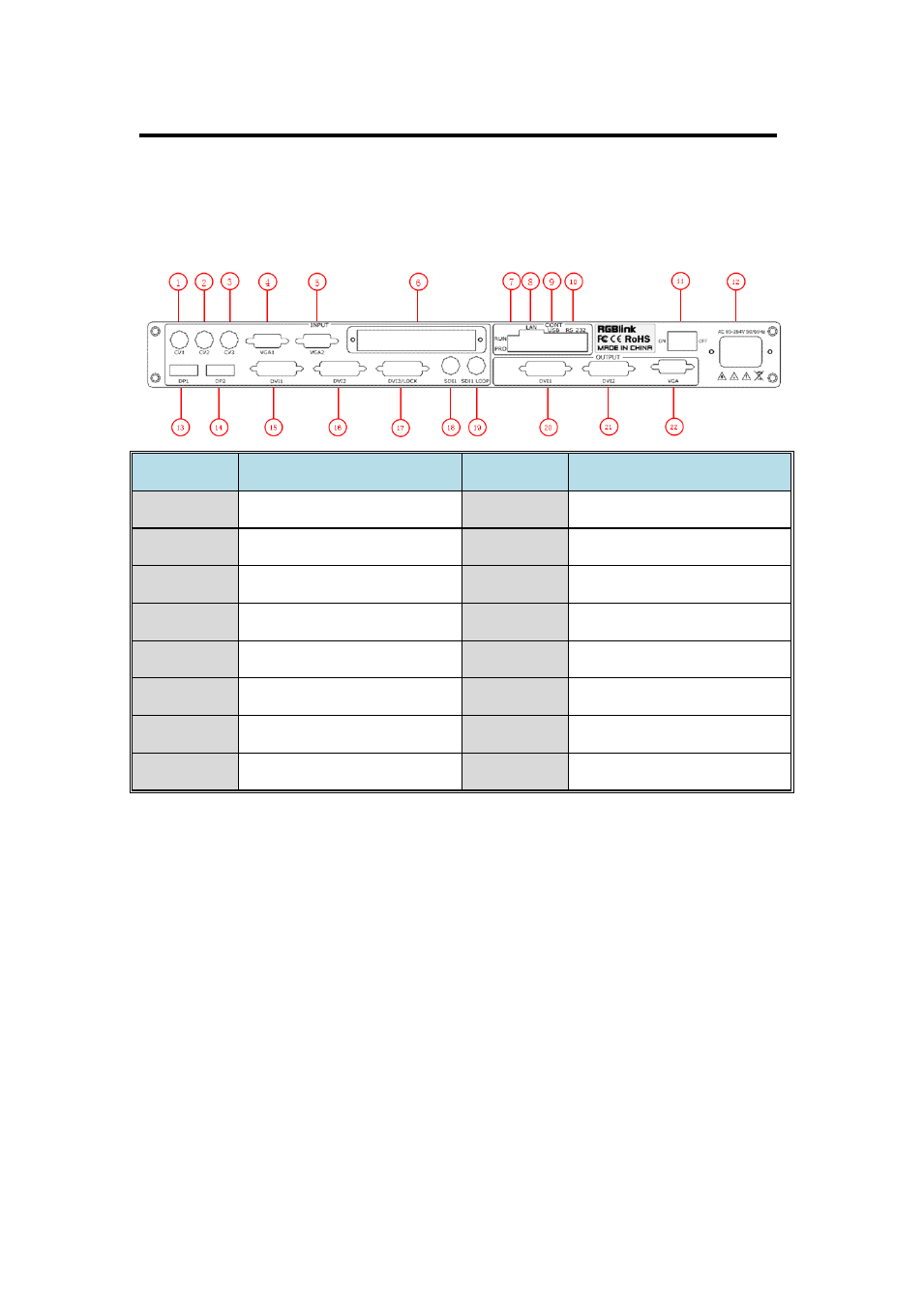
The figure below illustrates the professional interface and control signals of
VSP 5162PRO back panel.
NO
INTERFACE
NO
INTERFACE
1. 2. 3
CVBS Input BNC port
12
Power IEC-3 port
4. 5
VGA Input DB15
13. 14
Displayport Input
6
S. V. D. U Optional Module
15.16. 17
DVI Input DVI-I
7
Dial Switch
17
Lock Port
8
10/100M Interface RJ45
18
SDI Input
9
USB Interface
19
SDI Loop Out
10
RS-232 Interface
20. 21
DVI Output DVI-I
11
Switch
22
VGA Output DB15
20. 21. DVI output , use for connecting the sending card of LED display.
VSP 5162PRO support resolution format as following:
1024×768×60, 1280×720×60, 1280×768×60, 1280×800×60,
1280×1024×60, 1360×768×60, 1366×768×60, 1400×1050×60,
1440×900×60, 1600×1200×60, 1680×1050×60, 1920×1080×60,
1920×1200×60, 2048×1152×60, 2560×816×60.
22. VGA output, connect the display or other device with VGA interface:
1024×768×60, 1280×720×60, 1280×768×60, 1280×800×60,
1280×1024×60, 1360×768×60, 1366×768×60, 1400×1050×60,
1440×900×60, 1600×1200×60, 1680×1050×60, 1920×1080×60,