8 pump group layout, Remko pump groups hgm / hgu – REMKO HGM-HGU User Manual
Page 20
4.8
Pump group layout
The distribution group with the motorised mixing
valve can also be connected in a way that differs
from the standard installation (inlet on the right and
at the top). The possible installation configurations
depend on the type of pump installed. The connec-
tion options are shown in the diagrams below.
2
4
3
1
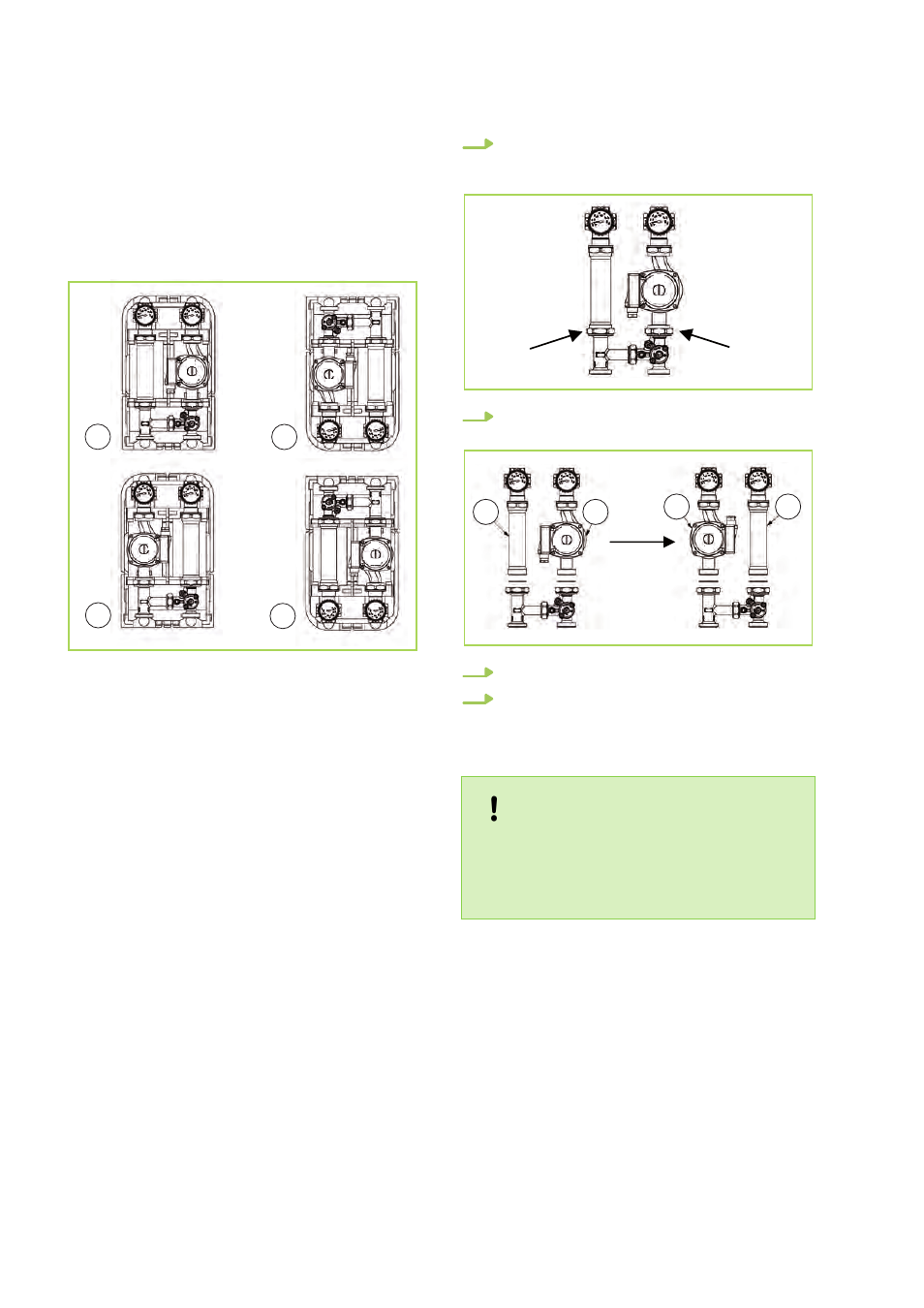
Fig. 10: Pump group layout
1-4: Diagrams 1-4
As shown in diagram 1, the distribution group with
the motorised mixing valve is delivered in the
standard configuration; this means that the pump
is on the right and the inlet on the top. The heating
cycle group can be configured using the process
shown in diagrams 2, 3 and 4.
1.
Loosen the rotary valves (see the arrow) and
uncouple the extension (2). Ensure that the
flange is flat-sealing.
2.
Transpose the installation positions of the
pump (1) and the extension (2).
2
1
2
1
3.
Insert the flat seal and close the valves.
4.
If necessary, turn the pump motor (this
applies to pumps that enable the motor to be
aligned).
NOTICE!
Leave the ball valve with the red grip on the
inlet with the pump and the ball valve with the
blue grip on the return flow due to the flap
valve. Adhere to the flow direction of the pump.
REMKO PUMP GROUPS HGM / HGU
20