Remko pump groups hgm / hgu – REMKO HGM-HGU User Manual
Page 14
6.
Install the pump group wall bracket on a suit-
able wall. The wall bracket is equipped with
long holes to aid height adjustment. Fix the
wall bracket to the wall using the enclosed
wall plugs.
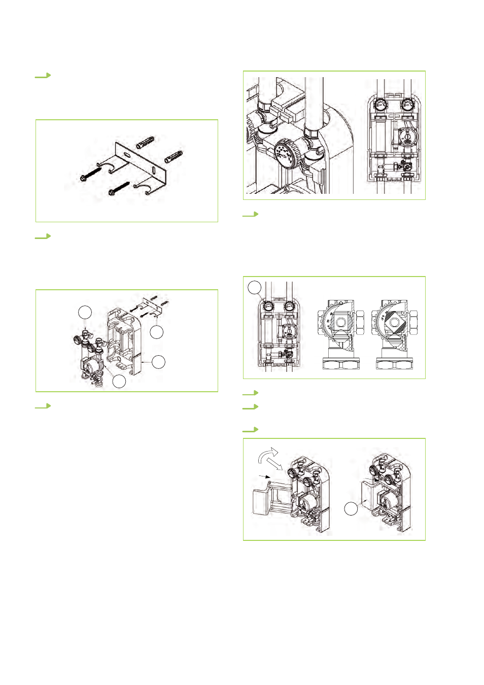
7.
Attach the rear side (2) of the insulation half-
shell to the wall bracket. Install the inlet (4)
and the return flow (5) on the wall bracket by
lifting the insulation slightly. So, the distance
between the pipe axis and the wall surface is
around 54 mm.
2
4
5
6
8.
Use the screw connection enclosed in the
packaging to install the piping for the inlet
and the return flow; ensure that the connec-
tions are suitable for the pipe dimensions
(connections with flat seals are recom-
mended). If a pump is connected in a series
to the pump group (e.g. boiler pump), in prac-
tice, a fixture to separate the heating cycles
hydraulically is to be installed, in order to pre-
vent a malfunction of the two pumps or the
heat pump.
9.
Turn the regulator of the return flow's ball
valve (7) to an angle of 45°; in this position,
the ball valve bypasses the check valve and
nullifies the effect of the valve. This enables
the water and the air that is to be bled in the
filling phase to flow better. Fill the system
and check for leaks.
7
10.
Open the ball valve of the return flow (7).
11.
Install the electric cables (see the positioning
of the cables section).
12.
Insert the pump's insulation (3).
3
REMKO PUMP GROUPS HGM / HGU
14