Wiring diagram, Prior to initial operation, Condensation connection – REMKO ML 260 User Manual
Page 19
19
Connecting the outdoor unit
Prior to installing the connection, observed the follow-
ing:
The customer must install the con-
trol box close to the outdoor unit.
We recommend using a main or
repair switch.
Power is supplied to the indoor unit
via the connection line from the
outdoor unit.
The system’s electrical fuse protec-
tion must comply with the technical
data.
Proceed as follows to connect the lines:
1. Remove the cover above the shut-off valves.
2. Select the diameter of the connection line(s) based
on the requirements.
3. Guide the connection line and the control line to the
unit.
4. Connect the lines according to the wiring diagram.
5. Place the line securely in the strain relief and reas-
semble the unit.
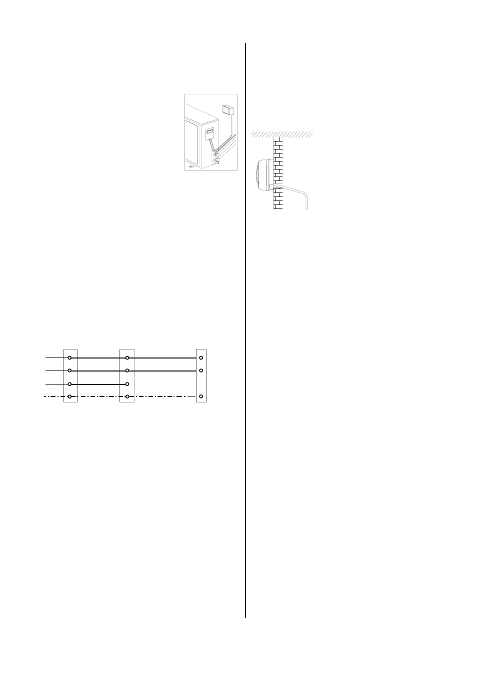
Wiring Diagram
Outdoor unit
Compressor contact
Protecting earthing
conductor
Power supply
Indoor unit
L
N
7
L1
N
L
N
7
PE PE
PE
Neutral conductor
Phase conductor
230 V~,
50 Hz,
L1 / N / PE
Prior to Initial Operation
After the impermeability check has been performed, the
vacuum pump must be connected to the valve connec-
tions of the outdoor unit by means of the manometer
station and a vacuum must be created.
Prior to initial operation of the unit and after contact with
the cooling cycle, the following checks must be per-
formed and documented in the initial operation log:
Check all refrigerant pipes and valves for leaks with
a leak locator spray or soapy water.
This must be performed with the unit off.
Check the connection lines to ensure that the suc-
tion and injection pipes have not been reversed.
Check the refrigerant pipes and insulation for dam-
age.
Check that the condensation is draining properly.
Check that all additional components are functioning
properly.
Condensation pumps, etc.
Check the electrical connection between the indoor
unit and the outdoor unit for the correct polarity.
Check all fixtures and suspended parts to ensure
that they are in the proper position and at the correct
height.
*
If the refrigerant pipe is longer than 5 m, more re-
frigerant should be added to the system.
Condensation Connection
Condensation forms on the plate fin exchanger of the
indoor unit during cooling operation because tempera-
tures below the dew point are reached.
The indoor unit is equipped with a collection tray and a
condensation hose for the condensation that accumu-
lates.
Follow the instructions below to lay the condensation
hose:
The condensation drain is generally placed in the
same guideway as the refrigerant pipes.
If, as a result of structural design conditions, it is neces-
sary to have a different guideway for the condensation
drain, the hose can also be guided to the indoor unit
through a different drain.
2% incline
If the unit is being operated at outside temperatures be-
low 0°C, the pipes must be placed in such a way that
they are protected from frost.
Always use suitable hose clips.
If the condensation is being guided to a sewage
pipe, please install a siphon-like hose guideway
which acts as an odour seal.
Make sure there is an adequate
incline for drainage.
It must be at least 2%!
The supplied condensation
hose can be extended using
standard hoses.
Since condensation is created, the condensation
hose must be isolated.
After the hose has been laid, check to make sure
that condensation can drain freely.