Installation – REMKO ML 260 User Manual
Page 17
17
*
Only tools approved for use in cold conditions may
be used.
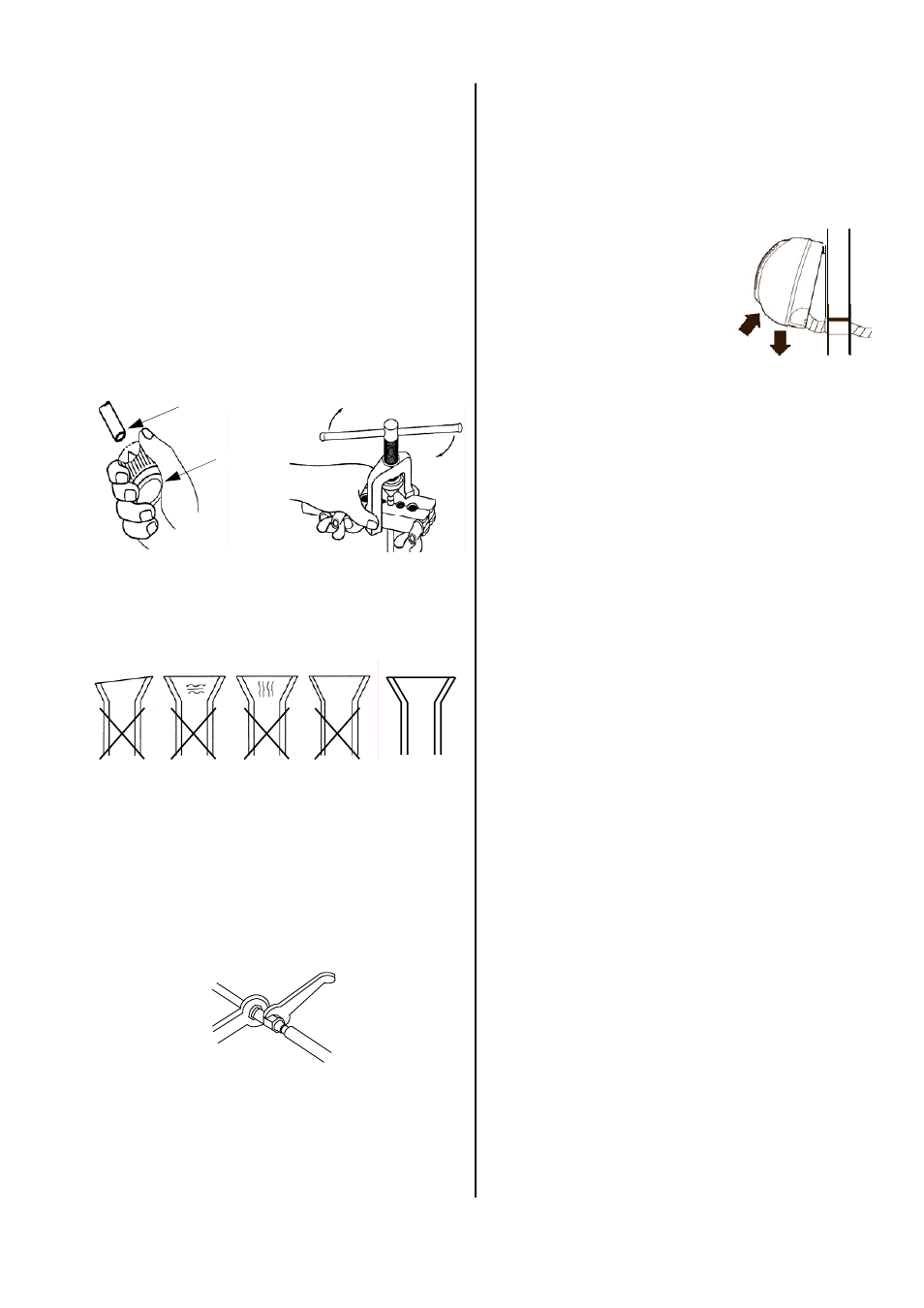
Pipe cutter, deburrer and flare tool.
Deburrer
Refrigerant pipe
Flare tool
uneven
thickness
formation
of cracks
formation
of cracks
rippled
CORRECT
6. Check that the flare has the correct shape.
7. First manually connect the refrigerant pipes with the
shut-off valves to ensure that they are in the proper
position.
8. Now tighten the bolts using 2 wrenches with a suffi-
ciently wide opening.
Use a second wrench to apply counterpressure
when tightening. (See figure)
Tighten
Wrench 1
Apply counter-
pressure
Wrench 2
*
If the length of the connection pipe is longer than 5
m, refrigerant must be added to the system during
initial operation.
See the “Adding refrigerant” section
.
Installation
The following instructions describe the installation of the
cooling cycle and the assembly of the indoor and outdoor
unit.
1. The required pipe diameters are provided in the
"Technical Data” table.
2. Begin with the installtion of the indoor unit.
3. Remove the supplied screw caps and use these for
continued assembly.
4. Before you flare the refrigerant pipes, make sure
that the screw cap is placed on the hose.
5. Work with the refrigerant pipes as shown in the
figure below.
11. Hang the indoor unit leaning
slightly to the back in the previ-
ously assembled wall mount
and press the bottom of the
unit into the mount.
Do not damage the pipes and
ensure that they are in the cor-
rect position.
12. Assemble the indoor unit in such a way that conden-
sation drainage is not blocked and air can always
flow freely in and out of the unit.
13. When assembling the unit, observe the bending radii
of the refrigerant pipes and never bend the hose in
the same place twice.
This may cause the pipe to become brittle or crack.
14. Place the refrigerant pipes between the indoor unit
and the outdoor unit.
Make sure that they are securely fastened and take
steps to recirculate the oil!
15. Install the outdoor unit with the wall or base console
onto stationery building parts approved for this pur-
pose.
Follow the installation instructions for the consoles.
16. Make sure that no structure-borne sound is transmit-
ted to parts of the building.
Structure-borne sound can be reduced through vi-
bration absorbers!
17. Now connect the refrigerant pipes to the outdoor unit
as described above.
18. Insulate both the installed refrigerant pipes and the
connector against heat.
19. Only use insulation hoses suitable for this tempera-
ture range that are sealed against diffusion.
9. If you have selected option 2 or 4 (drainage through
the wall), guide the condensation water pipe and
control line through the wall lead-through to the in-
door unit. If you also need a condensation pump, it
must be installed beforehand.
10. If, due to structural design conditions, it is not possi-
ble to guide the condensation pipe through as well,
make sure that the condensation can drain freely at
all times.