REMKO ML 260 User Manual
Page 16
16
Minimum distances for the indoor units
The distances required for smooth operation of the indoor
unit are specified in the following figure.
Dimensions in mm
120
120
200
1500
120
Minimum distances
These safety zones ensure that air can flow freely in and
out of the unit, that maintenance and repair work can be
performed and they protect the unit from damage.
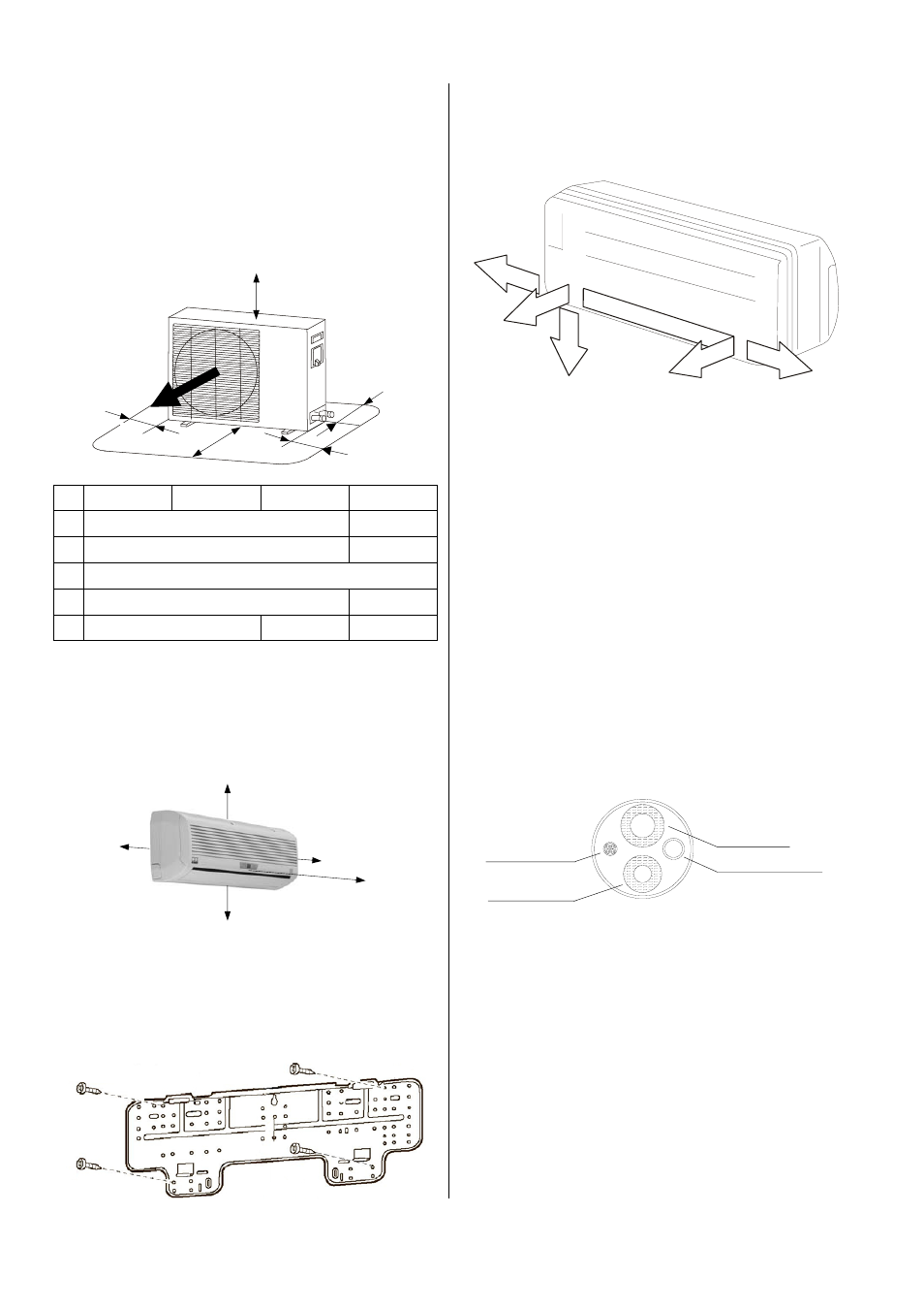
Minimum distances for the outdoor units
The figure below indicates the minimum distances that
must be maintained to ensure that the outdoor units oper-
ate properly.
ML 260
ML 350
ML 520
ML 680
A
100 mm
150 mm
B
700 mm
900 mm
C 400
mm
D
100 mm
150 mm
E
400 mm
600 mm
200 mm
Wall lead-throughs
Wall lead-throughs are necessary to establish the con-
nection between the indoor unit and the outdoor unit.
Please observe the following:
A lead-through of at least 70 mm in diameter must
be created.
The lead-through must be placed at an incline of at
least 10 mm between the inside and outside.
Before beginning work, make sure that there are no
supply pipes (water, etc.) located in the vicinity of
the wall lead-through.
We recommend cushioning the inside of the hole or
lining it with a PVC pipe to prevent damage to the
pipes.
Control line
Refrigerant
suction pipe
Condensation pipe
Refrigerant
injection pipe
If REMKO refrigerant pipes are used, the electrical
control line and the condensation pipe must be pro-
vided by the customer.
Therefore, the lead-through to be created must be
adapted according to the pipes provided by the cus-
tomer.
After assembly is complete, the wall lead-through
must be sealed with a suitable sealing compound.
Do not use any materials containing cement or lime!
A
B
E
C
D
Attaching the wall mount
The units must be attached with suitable screws and
dowels. The attachment points are displayed in the
following figure.
Lead-through options
Prior to installation, take a look at the various options
for lead-throughs of the refrigerant, condensation and
control lines (see figure below).
1 Opening on the wall right
2 Opening through the wall rear
3 Opening on the wall bottom
4 Opening through the wall rear
5 Opening on the wall left
3
4
2
1
5