Impermeability test, Electrical connection – REMKO ML 260 User Manual
Page 18
18
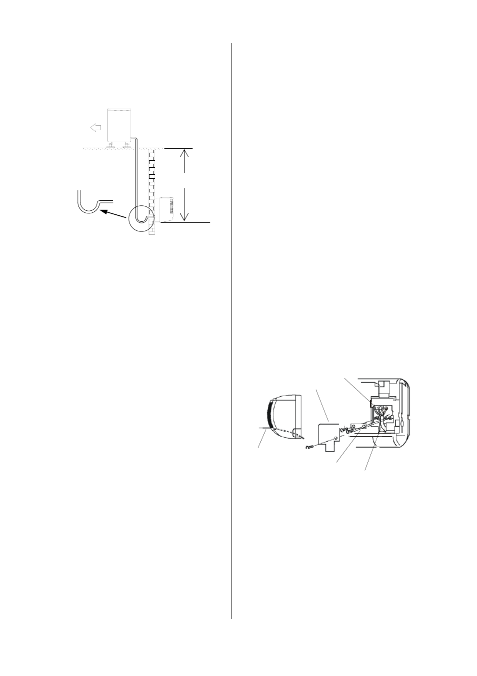
Oil recirculation
If the outdoor unit is set up at a higher level than the in-
door unit, appropriate steps must be taken for oil recir-
culation.
This is usually accomplished by creating an oil elevation
arc that is installed every 2.5 meters of pipe going up.
Radius:
50 mm
Outdoor unit
max. 8/10 m
Indoor unit
Oil elevation arc in the suction pipe
to the outdoor unit
1x for every 2.5 meters of
pipe going up
*
A vacuum with a minimum of 0.05 mbar must be
created!
*
Prior to performing any work on the unit, it must
be unplugged from the power supply and secured
against being inadvertently switched on!
How long it takes to create the vacuum is based on the
hose line volume of the indoor unit and the length of the
refrigerant pipes. However, this process takes a mini-
mum of 30 minutes.
Once foreign gases and moisture have been completely
removed from the system, the manometer station
valves are closed and the valves of the outdoor unit are
opened as described in the "Initial Operation" section.
Impermeability Test
Once all connections have been made, the manometer
station is connected to the corresponding valve connec-
tions as described below:
red =
small valve
= injection pressure.
blue =
large valve
= suction pressure.
After the connection has been made, an impermeability
test is conducted using dry nitrogen.
The connections that have been established are
sprayed with a leak locator spray to test for imperme-
ability. Tighten the bolts more firmly or, if necessary,
create a new flare.
After this test has been successfully conducted, any ex-
cess pressure is removed from the refrigerant pipes and
a vacuum pump with an absolute final partial pressure
of at least 0.01 mbar is put into operation to create a
vacuum in the pipes. This also removes any moisture
from the pipes.
Electrical Connection
All electrical installations may only be performed by
authorised service centres in line with the relevant regula-
tions. Local guidelines for operation as well as the re-
quirements established by local energy supply compa-
nies must be observed for setup and initial operation.
The diameter of the power supply line is based on the
structural conditions and the power supply capacity of
the unit.
A power supply must be installed to the outdoor unit
and a 4-wire control line must be installed from the out-
door unit to the indoor unit.
We recommend using a shielded line with a diameter of
at least 1.5 mm² for the control lines.
Connecting the indoor unit
Prior to installing the connection, observe the following:
Power is supplied to the indoor unit via a control line
from the outdoor unit.
The system’s fuse protection must comply with the
technical data.
The terminals of the connections are located on the
right-hand side of the indoor unit.
Terminal
Cover
Strain relief
Control line
Control line
To connect the units, proceed as follows:
1. Open the air inlet grille.
2. Using a Phillips screwdriver, loosen the cover on the
right side.
3. Connect the unit to the current-free line from the
outer unit.
See Wiring Diagram.
4. Reassemble the unit.