Troubleshooting the pt-link controller, Pt-link ii lon, Technical guide – Orion System PT-Link II LON User Manual
Page 14: Pt-link ii interface 14, Pt-link ii board leds
PT-Link II LON
®
Technical Guide
PT-Link II Interface
14
Troubleshooting the PT-Link Controller
PT-Link II Board LEDs
The PT-Link II LON
®
is equipped with LEDs that can be used for
troubleshooting. There are eight LEDs on the PT-Link II board. See
Figure 20 for the locations of the LEDs on the PT-Link II board. The
LED descriptions and functions are listed in the following paragraphs.
POWER LED
When the PT-Link II LON
®
is powered up, the “POWER” LED should
light up and stay on continuously. If it does not light up, check to be sure
that you have 24 VAC connected to the board, that the wiring connec-
tions are tight, and that they are wired for correct polarity. The 24 VAC
power must be connected so that all ground wires remain common. If
after making all these checks the “POWER” LED still does not light
up, please contact WattMaster Controls Technical Support at our Toll
Free number—866-918-1100—for assistance.
LOOP LED
When power is applied to the PT-Link II LON
®,
the “LOOP” LED will
also light up. The LED should fl icker rapidly, indicating that the PT-Link
II is trying to communicate with the controllers on the loop. A “fl icker”
is defi ned as a brief moment when the LED turns off and back on. If the
“LOOP” LED does not operate as indicated above, fi rst power down
the unit and then reapply power. If this does not work, please contact
WattMaster Controls Technical Support at our Toll Free number—866-
918-1100—for assistance.
LED 1
When power is fi rst applied, “LED 1” will be off temporarily and then
will blink one time for each controller it is communicating with. For
example, if you have 4 controllers on the loop connected to the PT-Link
II , “LED 1” will blink 4 times. If the amount of blinks does not match
the number of controllers connected to the loop, it indicates there is a
communications problem. The best way to fi nd out which board is not
communicating is to go to each controller and look at its “COMM”
LED. The “COMM” LED should be solid and will fl icker occasionally
indicating communication with the PT-Link II LON
®
. If the “COMM”
LED does not fl icker, there is no communication with that controller.
LED 2
When power is fi rst applied, “LED 2” will be off temporarily and then
will blink slowly indicating that the PT-Link II baseboard is com-
municating with the ProtoCessor Module. If “LED 2” does not blink,
check that the ProtoCessor Module is installed correctly on the PT-Link
II baseboard and that the “PWR” LED is lit up on the ProtoCessor
Module.
PROTO LED
When the PT-Link II is fi rst powered up, the “PROTO” LED should
light up and blink continuously. This LED verifi es communication with
the board and the ProtoCessor. If the LED doesn’t light up, check that the
ProtoCessor is installed correctly and fi rmly connected to the Base Board.
The “PWR” LED should also be lit on the ProtoCessor Module.
TIMER LED
The “TIMER” LED is used for troubleshooting by WattMaster Controls
Technical Support. The “TIMER” LED should always be blinking
steadily.
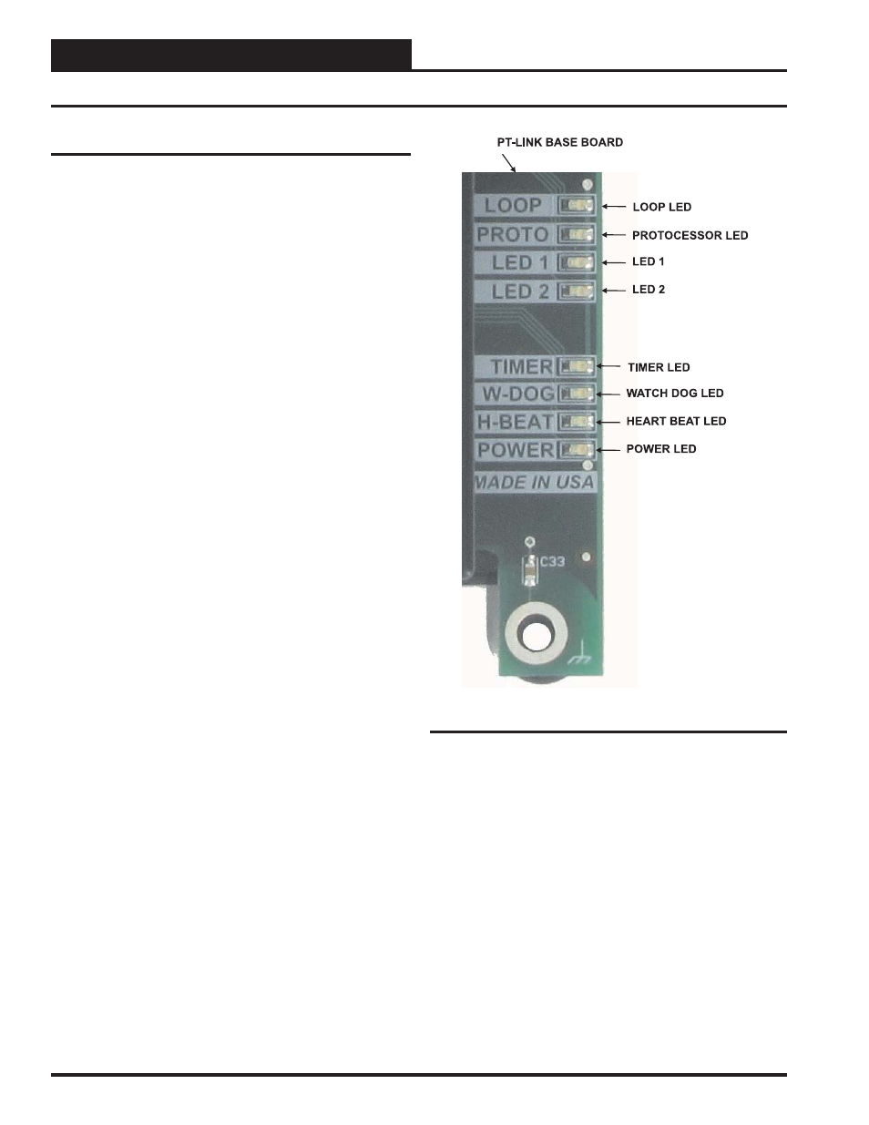
Figure 20: PT-Link II LON
®
LED Locations
WATCH DOG LED
The “W-DOG” LED is used for troubleshooting by WattMaster Controls
Technical Support. The “W-DOG” LED should always be on solid.
HEARTBEAT LED
The “H-BEAT” LED blinks to show the PT-Link II board software is
running. If the LED doesn’t light up, and all other checks have been
made, please contact WattMaster Controls Technical Support at our Toll
Free number—866-918-1100—for assistance.
Revised 1/14/10