Appendix a - sample confi gurations, Lead/lag example - controlling 3 sets of pumps – Orion System Lead Controller User Manual
Page 44
Appendix A - Sample Confi gurations
Lead/Lag Controller Technical Guide
44
Lead/Lag Example - Controlling 3 Sets of Pumps
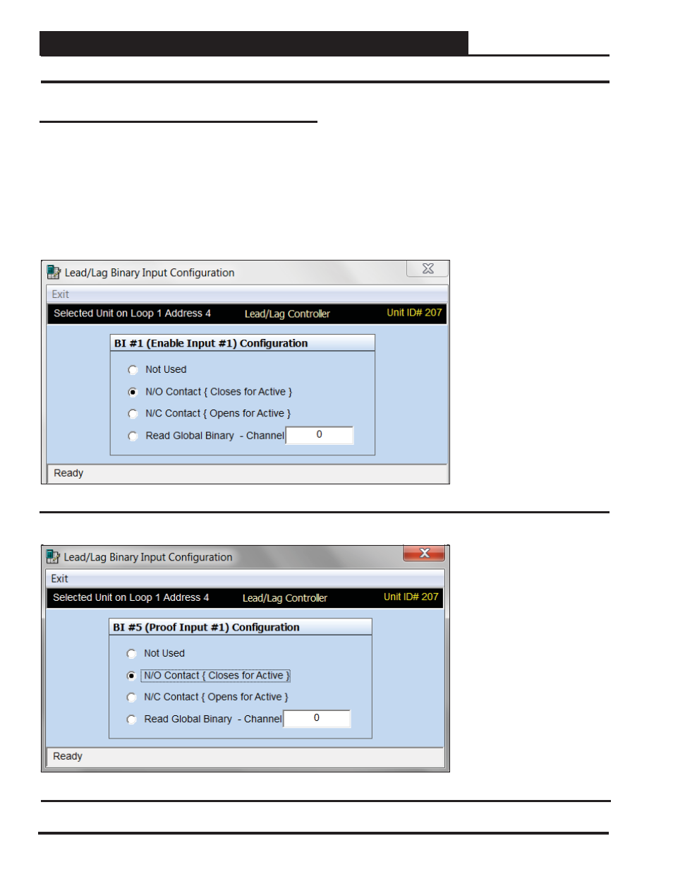
Binary Input Confi guration
Binary Enable Input #1 is a switch that can start and stop the boiler
pumps.
Binary Enable Input #2 is a switch that can start and stop the chiller
pumps.
Binary Enable Input #3 is a switch that can start and stop the do-
mestic pumps.
Figure 82: Binary Enable Input 1 Confi guration
Figure 83: Binary Proof Input 1 Confi guration
Binary Proof Input #1 is a water fl ow switch for the boiler pumps.
Binary Proof Input #2 is a water fl ow switch for the chiller pumps.
Binary Proof Input #3 is a water fl ow switch for the domestic water
pumps.
See Figure 82 for the confi guration for Binary Enable Input #1 and
Figure 83 for the confi guration for Binary Input Proof #1.