Components and navigation – Orion System Lead Controller User Manual
Page 17
Lead/Lag Controller Technical Guide
Section 5: Confi guring Binary Inputs
17
Components and Navigation
Binary Inputs
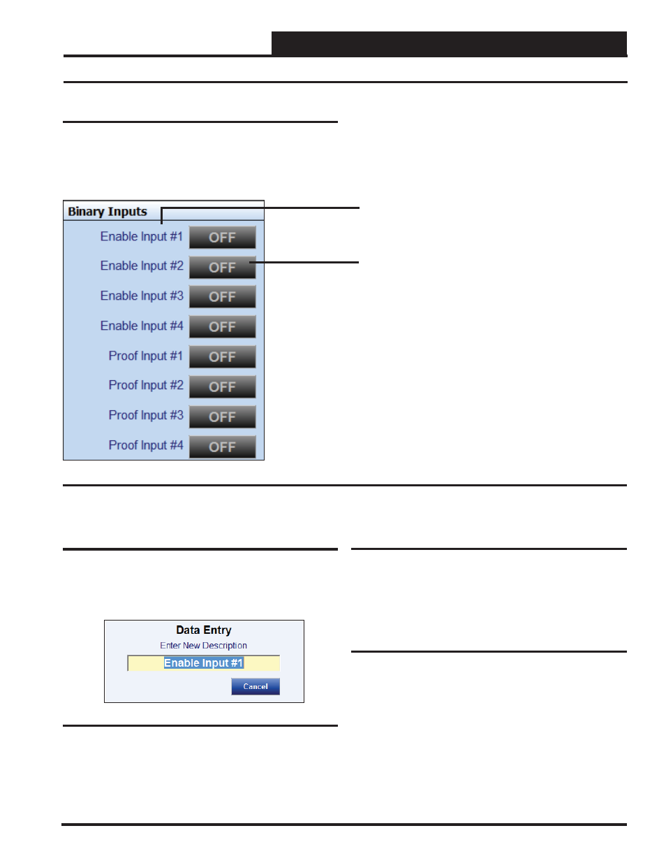
The Binary Inputs Window is located in the upper center of the Lead/
Lag Controller Status Screens (Figures 8 & 9, pages 11 & 12). There
are 8 Binary Inputs. Binary Inputs are used as either Enable Inputs
or Proof Inputs. These Binary Inputs are 24 VAC wet contacts. See
Figure 19 for the Binary Inputs Window component details.
Figure 19: Binary Input Window Components and Navigation
Renaming Binary Inputs
To give the Binary Input a new name, click on the blue highlighted
Binary Input # fi eld and the Binary Input Data Entry Dialog Box
will open (Figure 20). Once you have typed in a new description
(max 17 characters), press
to save.
Figure 20: Binary Input Data Entry Dialog Box
Right or Left-click on any of the Binary Input name
fi elds to access the description entry box to add or
change the name of the Binary Input.
Left-click on the Status box to confi gure the Binary
Input.
Right-click to override the Binary Input.
Enable Inputs
The fi rst 4 Binary Inputs are Enable Inputs—Inputs #1-#4. Enable
Inputs can be used to activate the Lead/Lag devices. Confi guring
the Lead/Lag devices to use the Enable (Activation) Inputs is done
in the Relay Confi guration Screens.
Proof Inputs
The last 4 Binary Inputs are Proof Inputs—Inputs #5-#8. Proof Inputs
are used to prove that the devices are operating correctly. They can
be such things as air fl ow switches, water fl ow switches, or pressure
differential switches. Confi guring the Lead/Lag devices to use the
Proof Inputs is done in the Relay Confi guration Screens.