Analog inputs – Orion System Lead Controller User Manual
Page 13
Lead/Lag Controller Technical Guide
Section 4: Confi guring Analog Inputs
13
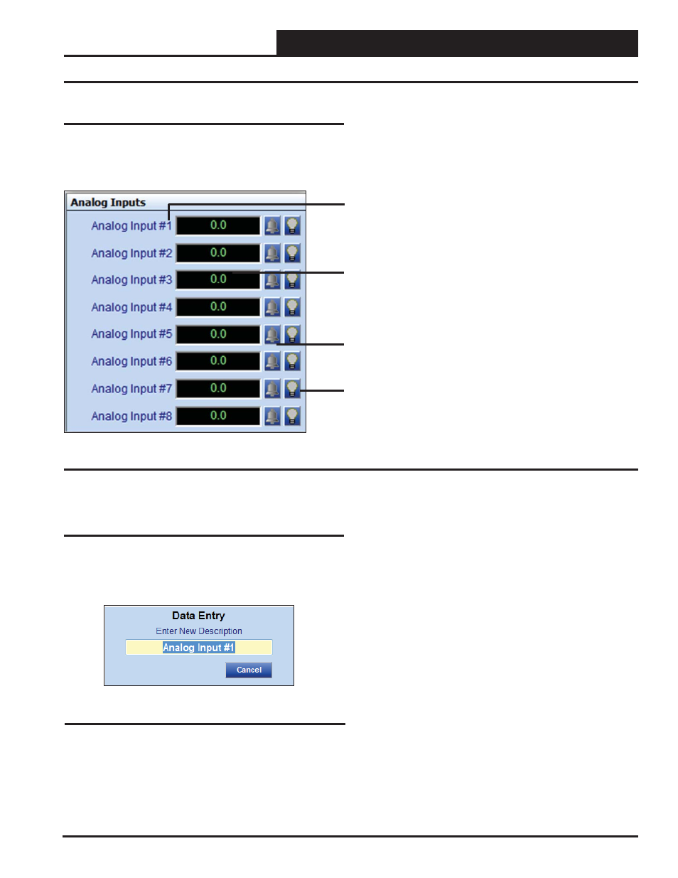
Analog Inputs
Analog Inputs
The Analog Inputs Window is located in the upper left-hand side of
the Lead/Lag Status Screens (Figures 8 & 9, pages 11 & 12). There
are 8 Analog Inputs. See Figure 10 for the Analog Inputs Window
component summary and the pages that follow for details.
Right or Left-click on any of the Analog Input name
fi elds to access the description entry box to add or
change the name of the Analog Input.
Left-Click in the data entry fi eld to confi gure the Analog
Input.
Right-Click on these fi elds to access the Calibration,
Override, and Clear Override.
The bell will light up to indicate that an alarm is on.
The Light bulb will light up when the Input is in the
Occupied Mode.
Figure 10: Analog Input Window Components and Navigation
Renaming Analog Inputs
To give an Analog Input a new name, click on the blue highlighted
Analog Input # fi eld and the Analog Input Data Entry Dialog Box
will open (Figure 11). Once you have typed in a new description,
press
to save. The maximum number of characters is 17.
Figure 11: Analog Input Data Entry Dialog Box