Online power, Appendix a: summary of indicators and controls – OnLine Power Telecommunication User Manual
Page 44
OnLine Power
A-1
REV A
Appendix A: SUMMARY OF INDICATORS AND CONTROLS
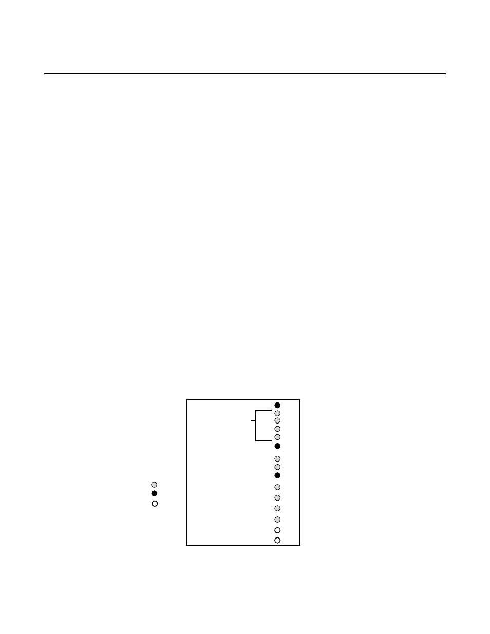
Status Indicators
The unit has two major components, the Electronic Tray and Battery. The Electronic Tray contains the battery
charger, breakers, receptacles, LED status panel, Inverter circuitry, and the input/output terminals. Each of the two
lower tray holds four batteries on each shelf. The lights on the LED status panel (at the front panel display) indicates
the unit’s operational mode. These lamps provide a positive visual indication of specific aspects of the unit’s
functional operation. These are as follows:
OVERLOAD (Red LED)
The output load is over 100% of rated load.
100% (Green LED)
Full load of 100% rating.
(Green LED)
75% of rated load.
(Green LED)
50% of rated load.
25% (Green LED)
0 to 25% of rated load.
SUMMARY ALARM (Red LED)
Illuminates when unit shutdown alarm condition is present
such as over temp., output short circuit, output overload, &
DC
overvoltage
HIGH BATTERY CAPACITY (Green LED)
Indicates the batteries are fully charged
MEDIUM BATTERY CAPACITY (Green LED)
Indicates the batteries are half charged
LOW BATTERY (Red LED)
Indicates the battery is approaching low shutdown level.
ON BATTERY (Green LED)
Indicates the battery is ON, and output is supplied from battery.
BYPASS ON (Green LED)
Indicates the unit is running with AC input power in OFF Line,
AC Mode, in Bypass.
INVERTER ON (Green LED)
Indicates the unit is running with the battery power in Inverter
mode.
INPUT AC ON (Green LED)
Indicates the input power is present.
UPS OFF S1
Used only to shut-off UPS when unit is running in DC mode.
UPS ON S2
Used only to turn on UPS when unit is running in DC mode.
INPUT AC ON
RED
GREEN
OVER LOAD
INVERTER ON
100%
25%
SUMMARY ALARM
HIGH BATTERY CAPACITY
LOW BATTERY
BYPASS ON
MEDIUM BATTERY CAPACITY
ON BATTERY
UPS ON S2
UPS OFF S1
SWITCH
LOAD IN
PERCENTAGE
OF RATED AMPS
ELECTRONIC TRAY - STATUS PANEL