Cable connections and wiring, Radio unit (ncu or remote) – NavCom SR-7120 Rev.A User Manual
Page 59
Safari Network User Guide
3-13
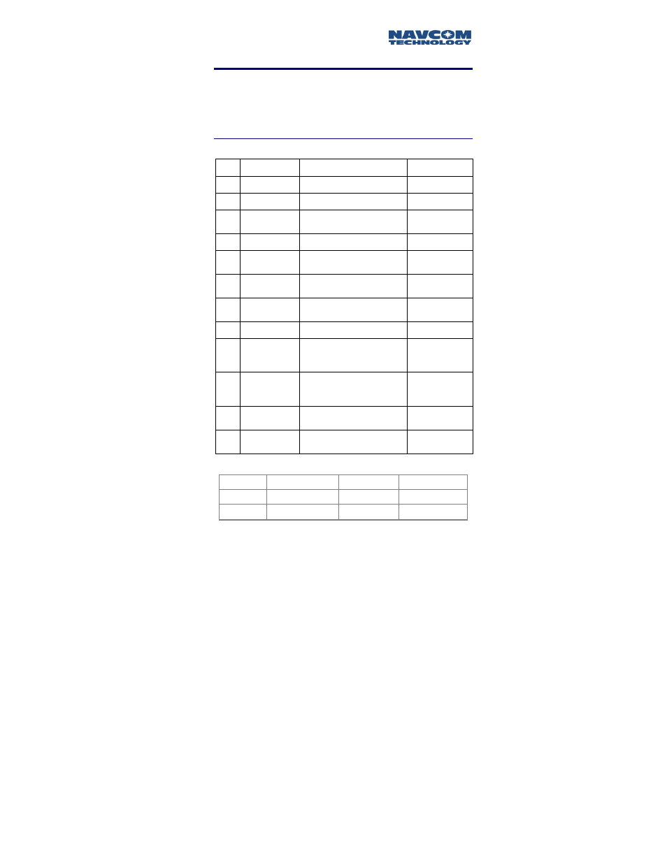
Cable Connections and Wiring
When a Port Expander will not be used, such as when a
radio unit is mounted on a vehicle, refer to Table 3-4 for
pin assignments and associated cable wiring.
Radio Unit (NCU or Remote)
J1 Signal
name
Functions
Cable
wiring
Pin 1 GND Chassis Connect to chassis ground Black, 20 gauge
Pin 2
Ext Vin
9-36 V DC power in
Red, 20 gauge
Pin 3
Auto On
Disable
See note 1
White/Blue
CAT 5
Pin 4
GND IO
COM3, ground
Blue, CAT 5
Pin 5
RS232 In
COM3, connect to TxD
on DTE
White/Green
CAT 5
Pin 6
RS232 Out
COM3, connect to RxD
on DTE
Green, CAT 5
Pin 7
CAN L
CAN bus
White/Brown
CAT 5
Pin 8
CAN H
CAN bus
Brown, CAT 5
Pin 9
NetSync B
For NCU synchronization,
to NetSync B on
other NCUs
White/Orange
CAT 5
Pin
10
NetSync A
For NCU synchronization,
to NetSync A on
other NCUs
Orange, CAT 5
Pin
11
Vin RTN
Ground for 9-36 V DC
power
Green,
20 gauge
Pin
12
IGN Main
See Note 1 below
White,
20 gauge
Table 3-4: J1 Cable Connector, NCU and Remote
Note 1.
Radio status
Pin 12 high
Pin 12 low
Pin 3 open
Power ON
Power OFF
Pin 3 grounded
Power ON
Power ON