Appendix b - wiring diagrams, Appendix b, Wiring diagrams – MicroE OPS Series User Manual
Page 20: Connector pin configuration, Grounding considerations, Recommended signal termination, Page 20, Digital outputs, Standard rs-422 line receiver circuitry
Page 20
Appendix B
Wiring Diagrams
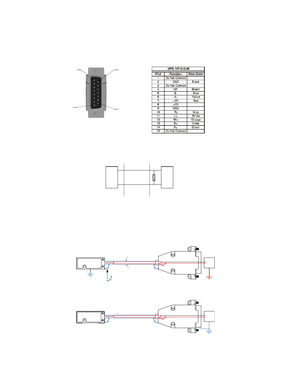
Connector Pin Configuration
!
!
5
!
'
!
O.P.S. 15P D-SUB
P
5 Volts
0 Volts
Electrically conductive mechanical
connection (as supplied by MicroE
Systems).
POWER
SUPPLY
INNER SHIELD:
Insulated from outer shield, sensor case, and
connector housing. Connected to circuit common
internally as supplied by MicroE Systems
OUTER SHIELD: Connected to
sensor and connector housing
5 Volts
0 Volts
POWER
SUPPLY
Grounding Considerations
Sensor mounted with good electrical contact to well grounded surface (preferred):
Sensor mounted to poorly grounded or non-conducting surface:
NOTE: GND and INNER SHIELD ARE INTERNALLY CONNECTED.
Max cable length: 5m. Contact MicroE Applications Engineering if longer length required.
Recommended Signal Termination
Cable Zo=
120 W
OPS Series
Encoder
Customer
Electronics
120
W
+
-
Digital Outputs:
A, B, I
A, B, I
Standard RS-422 Line Receiver Circuitry